Misc. YJ vs CJ prop valve

Misc. YJ vs CJ prop valve

Masscj7

Senior Jeeper
Lifetime Supporter
Posts
728
Media
10
Thanks
73
Location
West Springfield, MA
Vehicle(s)
1986 CJ7, SBC 350, Dana 300, D30, AMC20
Anyone know electrically how the dual pin plug YJ prop valve circuit works versus the single pin CJ. Or am I wrong. Looks like by surfing online, the CJ prop valve issues a single pin plug and the YJ a dual pin. Looks the PO put on a YJ prop valve and I have a CJ harness and cluster.

From what I’ve read, the purpose of the plug has something to do with a brake system failure and I’m not exactly what indicator it lights up in the CJ Speedo cluster.


Sent from my iPhone using Tapatalk
 
Solution
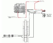
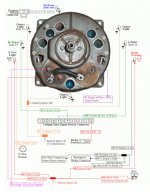
On a CJ the original prop valve also had two pins in the connector. Most replacements have a single pin connector (designated with "PV2" on them). On a single pin prop valve, the plunger inside the prop valve grounds the wire connected to it. On a prop valve with the two separate pins, the plunger does not ground the connection internally. It connects the two pins together like a switch. In the stock setup, one wire is a ground from the ignition switch and the other is the ground or negative side of the warning light in the dash. When you turn on the ignition, you apply +12V to the positive side of the dash warning light and the ignition switch applies the ground connection to one of the two black wires going to the prop valve. If the...
On a CJ the original prop valve also had two pins in the connector. Most replacements have a single pin connector (designated with "PV2" on them). On a single pin prop valve, the plunger inside the prop valve grounds the wire connected to it. On a prop valve with the two separate pins, the plunger does not ground the connection internally. It connects the two pins together like a switch. In the stock setup, one wire is a ground from the ignition switch and the other is the ground or negative side of the warning light in the dash. When you turn on the ignition, you apply +12V to the positive side of the dash warning light and the ignition switch applies the ground connection to one of the two black wires going to the prop valve. If the prop valve sees a lack of pressure or too large a differential of pressure between front and rear lines, the plunger will connect the two pins together. This completes the circuit and turns on the brake warning light in the dash. Of course the ebrake also has a grounding wire that connects to the negative side of the warning light so that applying the ebrake also tuns on the light. When switching to a "PV2" style aftermarket prop valve, you simply connect the black wire from the negative side of the warning light and ignore the ground wire from the ignition switch. This is because the prop valve will ground the one wire from the light inside the prop valve itself with no need for an externally supplied ground from the ignition switch. I don't have a wiring diagram for a YJ. Here's a diagram showing this wiring on a CJ. Also here's the wiring behind the gauge cluster showing the connections and where the brake warning light is located. When I did my push button start and eliminated my stock ignition switch, there was no provision for this additional switched grounding line to go to the prop valve. I already had a PV2 style prop valve and I also have a Dakota Digital gauge setup with the electronics module that drives the gauges. So a single ground wire to that single pin connector on the prop valve is all I needed. That other original black wire from the ignition switch through the junction block on the fuse panel is now used for another purpose where I needed a wire going through the junction block.

brake_warning_light_wiring.jpg gauge_cluster_wiring.jpg
 
Solution
TS,
They may have been one of the most thorough explanations I’ve ever seen. That absolutely cleared up my questions as just before I read this, I saw the two black ground switch wires on my firewall plug. You confirmed what I was thinking when I saw their descriptions. So my harness is set up for the 2 pin plug.
Thank you so much and fantastic explanation.


Sent from my iPhone using Tapatalk
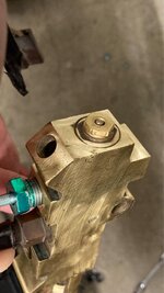
 
So I was able to find an OEM two pin plug on eBay so I have that coming.

My next question is as I look at processes for bleeding, it states you need a tool or make one to hold the valve open when bleeding it. When I look at my valve, it does not have the notched pin protrusion to be able to hold the valve open while bleeding. Is this a different style of valve? No need to manipulate the valve when bleeding?

daaf4333270dfd0c969047571eba1e5e.jpg


Sent from my iPhone using Tapatalk
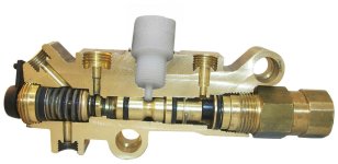
 
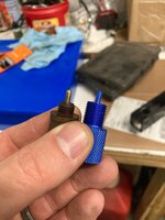
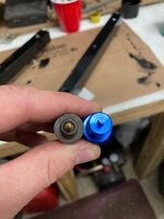
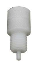
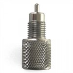
The tool they are referring to is a plastic (or metal) insert that screws in place of the sensor switch. You have that plunger in the center of the valve that moves side-to-side with pressure (front to back) and if it moves too far one way or the other, it allows the spring-loaded switch to close the contacts (turning on the light). Obviously when you bleed the brakes you are bleeding the back first (do the furthest wheels first) and then the front. This means you are applying uneven pressure to rear and then separately front lines. So when you bleed the brakes, you want to remove the sensor switch and screw this tool into that hole. The tool holds the plunger centered in place until you are done. Then you remove the tool and screw the sensor back in. Now you know the sensor will be centered and not too far one way or the other inadvertently. It is NOT in the end of the prop valve like you are showing in your picture. It is in the center of the top where the sensor is that you connect the wires to. Check out the white plastic tool in the top center of this prop valve in the picture. I've seen these tools in both plastic and metal. Metal makes more sense if you use one frequently, as repeated use of the plastic may booger up the threads. You can even download a file to 3D print one if you the printer. Also here's a shot of a plastic and one of a metal tool.

tool.jpg tool_plastic.jpg tool2.jpg

Here's a great link to get a tool and watch a how-to video: Centering tool

And here's a just a tool on Amazon: Centering tool
 
Once again TS, you’re the man! Wish you were the neighbor next door hanging out in the garage having a beer and overseeing! Thank you very much sir!


Sent from my iPhone using Tapatalk
 
“& I am buying the first round”. Using a phrase from a fellow work colleague.
 
Well it found a couple of things, all the centering tools I can find online appear to be PV2 style which is 1/2” diameter Way too big for my valve, which is 3/8”.

6105e2f51d2c6180913512fc0aae11cf.jpg
51245f9978d7394c14241953e496384a.jpg

It also appears as my switch is bad, as I have continuity even when the plunger isn’t depressed. So thinking I might as well get a whole new set up that will be a PV2 fitting size and be able to use the appropriate tool. More money I guess.


Sent from my iPhone using Tapatalk
 
"It also appears as my switch is bad, as I have continuity even when the plunger isn’t depressed. So thinking I might as well get a whole new set up that will be a PV2 fitting size and be able to use the appropriate tool. More money I guess."

My prop valve was leaking. But replacing with a new one was also my best route as well. I have heard from some guys that they used a leather punch or other "poker" to stick into the hole and hold the plunger centered (with a helper) when no tool was available. I also saw online one example where a person took a bolt of the correct size/threads and ground down the tip of it to a rounded point to make a homemade tool. In the absence of a lathe, maybe you could chuck a bolt up in a drill press and then use a grinder or file to do the shaping.
 

Jeep-CJ Donation Drive

Help support Jeep-CJ.com by making a contribution.

Help support Jeep-CJ.com by making a contribution.
Goal
$200.00
Earned
$25.00
This donation drive ends in
Back
Top Bottom