• Hello Guest, we are proud to now have our Wiki online that is completely compiled and written by our members. Feel free to browse our Jeep-CJ Wiki or click on any orange keyword when looking at posts in the forum.
    To dismiss this notice
    click the top right X.

Build Thread Build a New Set of Gauges from Scratch

Build Thread Build a New Set of Gauges from Scratch

DHugg

Senior Jeeper
Posts
915
Media
46
Resources
1
Thanks
2
Location
MS Gulf Coast
Vehicle(s)
'80 CJ7 304AMC crate with 8KMiles: MC2100 - AMC20 rear w/Superiors - Dana30 front - TF999 - Dana300TC - 35x12.5's - Tilt steer column - Flaming Rvr EZ-Steer Shaft - AGR Super Pump - AGR Super Box II - RockyRidge HD Brace - New home-designed digital TEMP - GAS - OILPR - CALIBRATE gauges.
I was all set to be seriously miffed that my second full attack on an inoperable set of gas and temp gauges had failed. The Crown gauge replacement set had a dead short in the fuel gauge. Two blown 3 amp fuses and I'm outta here!

But after a few minutes' pondering, I've decided I can build my own gauges from scratch; so can you. But of keeping your Jeep all original is deadly important to you, read no further. As for me, OEM where applied to gauges means never works, never has.

I'm starting with the temperature gauge, and the only thing original I'll reuse is the hot coolant inside the water jacket. I'll build a simple but stable and cheap 9VDC power source. The pickup will be a digital device, packed inside a threaded and drilled well that uses one of the pollution-control heat sensor sockets, named DS18B20 that puts out a message on a single wire that is decoded by a tiny computer board called an ARDUINO. The Arduino will drive a liquid-crystal display (LCD) that displays two lines of 20 characters each, white on blue. That's my choice, but there are others.

If this seems complicated to you, just hang around for a while. All us Jeep wrench-benders are so used to iron and steel hardware that anything electronic is disgusting and distasteful. The advantages for me are these:

1. The gauges work.
2. Everything that comes after the temp gauge is easier by 2/3. every gauge you have, and some you don't have but only see in your dreams can be made following this same pathway. The only thing different is the sensor and where you pick off the data you want to use.
3. Low power devices, fused and protected both by diodes against accidental polarity reversal, and by thermal shutdown built into the power supply, will never (never say NEVER; say HARDLY IF EVER) fail you.
4. You can set any level of precision and rate of display update that you want.
5. Have I said cheap yet? I shoulda lead off with that point.

The prototype, operating right now on my desk, looks like the first picture attached. I'm building the power supply right now, using the schematic in attachment two. I'll post details, probably more than you want or need, tomorrow.

 
Last edited by a moderator:
Im going to leave this thread in the build forum for now. If everything works out I'll make it a sticky in the Electrical , body and chassis forum.
 
Re: Build a New Set of Gauges: What're we doing and why?

I've never in five years had an operable fuel or temp gauge. I don't know which I need the worst.
jeepgauges.jpg

This is the OEM Fuel gauge, burnt to a crisp. Without its power reducer to feed five volts to the temp gauge, no temp reading is available. After installing a set of Crown replacement gauges and finding a dead short inside the case, two blown 3AMP fuses later, I decided not to repeat past mistakes. I'm going to build my own gauge set from a microcomputer and hobby electronics parts.

I'd like to record the steps here in case you have a need or desire for a new gauge or gauge set.

Military trainers are taught a simple method for passing along information. It is "Tell 'em what you're going to tell 'em. Tell 'em! Tell 'em what you told 'em." Here goes...................

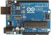
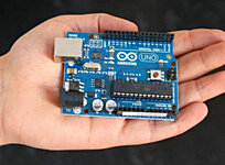
There is a tiny microcomputer on the market, designed with so much capability that there is almost nothing that can't be done with it. The name of the least expensive version in "ARDUINO UNO R3".

arduinouno_r3_front_1800.jpg

Inexpensive means $25 bucks. To set up a project, the Arduino free software should be loaded onto a laptop. A USB cable hooks you to the Arduino, into which you can plug any device known to man and control things. Specifically, you can hook up an Arduino Uno to the circuit that passes a voltage through the variable resistor that is the Jeep engine heat sensor, and using software, convert the voltage to a temperature reading, and display it on your laptop.

To recap what I just said, the ante is $25 bucks to get in the game, and if you have a laptop, you need nothing else to be able to display engine temp, fuel quantity, oil pressure from your Jeep to the laptop.

To mount a liquid crystal display on your dash, you might need another $15 bucks in display hardware and cabling.
arduino_uno_r3-500x500.jpg

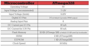
I plan to isolate my gauges from the engine power system by building a converter to knock down the 12 volts to 9 volts filtered, for lower heat dissipation. Look following at the Arduino power specs:
arduino_specs.jpg
The device will handle anything from six to 20 volts DC, but seven to twelve is recommended, and 9 volts is the sweet spot. The Arduino will operate readily from a 9VDC battery, and will operate off power from a USB port as long as devices hooked up aren't power-hungry.

In the next post, I'm going to load Arduino software on Windows XP and on a MAC. Few of us use Linux, although I like the operating system for the freedoms you get.
 
Re: Build a New Set of Gauges: What're we doing and why?

Can you run multiple sensors of a single board or do you need a new board for each sensor? I'd be interested in a single LCD scrolling display of temp, volts, oil pressure and fuel. I've looked at the Arduino boards before, but never got past the first look.

Can you post a more detailed wiring schematic and instructions when you get it all hooked up? Looks like a slick solution.

Peace!

I believe you can do exactly what you describe. We'd use four input pins, and scroll through the presentations, writing the titles in row1 (fuel, temp, oil, etc), selecting a delay of a few hundred milliseconds between each data set, then writing the measurements in row2 as each sensor title was presented.

Once you grasp what the Arduino people have built, its capabilities, things like this are really not a challenge. As I test my own electronic gauge install, I'll post every step along the path.

The more I think about how this all works with Jeep panels and power wires, the more I think I need hinges at the lower edge of the dash panel, so I just unlatch the top and side fasteners and fold down the dash flat on the hinges.
 
Re: Build a New Set of Gauges: What're we doing and why?

I've never worked with Arduino boards but have been curious about them for a while and really looking for an excuse to jump in. This project may just be what puts me in since I currently have non-working Fuel and temp gauges, a fuel sender that as far as I know works, a suspect volt gauge since it's reading what would look to be 20v with the engine running and a used oil pressure gauge that isnt currently in the Jeep and no idea if it works.

Good luck and keep us updated. Would just being behind the dash be sufficient to keep it out of the elements or would it need to be placed in a somewhat dry box?
 
Re: Build a New Set of Gauges: What're we doing and why?

Would just being behind the dash be sufficient to keep it out of the elements or would it need to be placed in a somewhat dry box?

jpeck71, behind the dash oughta be the best place for it. Thinking today about where the best view would be while driving..... I may put an extra overlay above the steering wheel, angled out at top, and store it all there.

Anyway, my dash is so chopped up that anything would be an improvement.
 
Re: Build a New Set of Gauges from Scratch : SOFTWARE

Here are the dealers who stick by the $25 dollar each price of an Arduino Uno R3. Some guys want up to $30 bucks, but hey, I've picked cotton for 5 cents a pound, and five bucks was a hard hustling day!

Vendors who sell for $25 bucks

Arduino : Adafruit Industries, Unique & fun DIY electronics and kits

(Link)-> Arduino - SparkFun Electronics -<

Arduino is a manufacturer of open-source microcontrollers and accessories. - RobotShop

Arduino Uno R3, ATmega328 USB Board

Arduino UNO USB Board R3

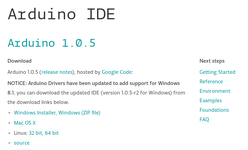
You can download and install the software for free any time you like, for the ARDUINO STORE SOFTWARE SECTION. Scroll down a little bit until you see the following display:

arduino_ide_download.png
When I installed into Windows earlier today, I simply accepted the default choices for where to locate the subdirectory Arduino, under Program Files. The install creates under the main Arduino directory a subdirectory named "libraries", and another named "sketchbook".

In Arduino parlance, a "sketch" is what we would call a program or a program file. The libraries allows the Arduino software to cache some necessary code where many of the "sketchs" can reach it on demand.

There are all kinds of help for Arduino operation on the 'Net. Here following is a guide for new Arduino users:

arduino_getting_started.png

Without an Arduino device hooked up, the software doesn't do much, but you can load sketches, open up the serial monitor window (spyglass in the upper right-hand corner).

If you encounter a red or orange error code while compiling a sketch that begins with "avrdude:....", as I did today, that means you have the wrong port selected for the SERIAL MONITOR. Go to TOOLS - SERIAL PORT and select another available port from the drop-down window.

The sketches are actually written in a subset of the "C" coding language, and are compiled by the Interactive Development Environment, or IDE.

Now that you've learned something that most of us wouldn't have noticed, here's another. Why would a C code program have a line in it like "void loop(); ??? Doesn't make sense the first time you see it. The term "void" means the program does not return any data when it is run, and the loop() is the main structure for getting things done, a merry-go-round that never stops, and each "horse" on the merry-go-round is a line or two that does work, turning something on, or off, or making a mathematical calculation or conversion that makes invisible events visible to us poor dumb humans.

There! The hard part is out of the way, I promise.

Tomorrow I expect to have the speedo back in the dash. I will isolate the two failed gauges but add wires that can connect to the Arduino. I actually expect to be able to "see' the different voltages on the SERIAL MONITOR as the engine temp thermistor warms up. I will take pictures, never fear.
 
Re: Build a New Set of Gauges from Scratch - Baselining

"Tell 'em what you'll tell 'em, Tell 'em, Tell 'em what you've told 'em!

THIS IS WHAT I'M GOING TO TALK ABOUT HERE.

It isn't necessary that you understand how Jeep gauges are built to function, and how the Arduino reads the original engine sensors and converts the reading to a presentation we can understand. You can skip this part if you have no interest, but I will be brief.

John Strenk did an excellent job describing both mode of operation and troubleshooting steps.
More on CJ Gauges - Jeep-CJ Documents and Manuals

Unfortunately there seem to be more ways for gauges to go wrong than there are ways to fix them; that's why it seems rational to take a new course. Here's how the OEM gauges worked, how the Arduino will work with the OEM engine temperature sensor, and how the hookup circuit will look with the Arduino driving the train. And we'll test with an analog volt-ohm meter both fuel and temp before hooking the Arduino into a running engine circuit.

TALKING ABOUT OEM GAUGE FUNCTION AND THE ARDUINO MICROCOMPUTER

The OEM gauges worked as current moved through a bimetalic strip, two metals that expanded when heated at different rates making the paired structure bend. The changes in the engine sensors, essentially variable resistors that passed more or less current depending on temperature, were represented as changes in gauge needle deflection when the bimetallic strip bent more or less. HOT more deflection, COLD less deflection. HOT more current, COLD less current. That translates to HOT less resistance in the engine temp sensor, COLD more resistance to current passage in the engine temp sensor.

here are the numbers taken from one of John Strenk's excellent works:

Jeep CJ TEMPERATURE GAUGE

Resistance Test:
73 ohms Cold - Test when engine is slightly warm. A stone cold engine will read 400 ohms
36 ohms Beginning of Band
13 ohms End of Band
9 ohms Hot

Resistance across temp gauge terminals= 21 ohms.

But the Arduino can't "see" resistance..... What we do now, Kemosabe?

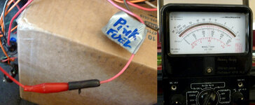
What we do now is hook up a volt-ohm meter between battery ground, or in the case of the engine temp sensor the engine block. and measure the resistance of the engine temp sensor at an ambient temp of 70 degrees, average early May garage temp here at 30 degrees North. And we'll use the same circuit to measure the fuel tank float resistor, to baseline all systems before moving on to the Arduino.

pink_wire___volt-ohm_meter.jpg


Well, it was interesting! The fuel tank resistor worked pretty much as expected; not 10 ohms full but 15 ohms full; I have driven around my neighborhood a few laps. Close enough for Government work; I can deal with that.

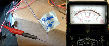
purple_with_trace___engine_cold.png


But when I hook up the engine temp sensor with the engine at ambient, I got an unexpected 3,000 ohms. Tech data says about 400 ohms cold; I'm way off!

I guess I'll solve one problem before I go chasing another. Tomorrow I'll test the old engine temp sender and a new one out of the circuit. I'll test them both in boiling water and see which is the bigger liar.

TELL 'EM WHAT YOU TOLD 'EM

You see here the very most basic description of how the temp and fuel gauges register under OEM engineering (????) design. Before we move to digital microelectronics, we should look at the circuits with analog meters to see what the starting condition will be, a method called "baselining". And lo, we find a surprise! The numbers for the temp sensor are way, way out of line.

Tune in tomorrow for another thrilling tale of yesteryear, when Jeep CJ's were built with the cheapest materials and the least skilled labor, just to get 'em out the door at a profit. And there ain't no Silver Bullet to fix them!
 
Re: Build a New Set of Gauges from Scratch - reading sensors

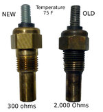
I found by checking resistance that my old engine temperature sensor was way, way off in resistance, Cold it read 2,000 ohms, and 5,000 ohms hot, instead of the 400 ohms cold down to 9 ohms hot.
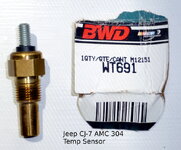
new___old_sensors.jpg
I bought a new one from O'Reilly's for 7 bucks. If you have gauge trouble, this is the easiest place to check.
wt691_jeep_cj-7_amc_304_heat_sensor.jpg
Since a careful check of sensors revealed a problem that would have stopped the train, I think I should go along more carefully in proving out the design of an Arduino reading existing OEM sensors and displaying readings on a liquid crystal display.

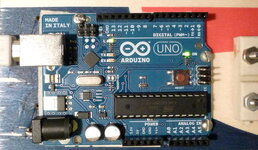
To start, I check out the Arduino against the Apple Macbook Air that will be mobile with the Jeep before the final hard-wire install. Using KISS, I run the very most simple software routine there is, to blink a small LED under program control. Looking at the top of an Arduino Uno, you can see a very small resistor just between the GND label and digital pin13. Right below the resistor and showing the letter "L" to the left is and LED.
fuelquanimportantleds.jpg
Over on the right under the UNO word is the power monitor LED. If this goes off, we're in a heap of trouble. To make LED13 blink, we need a SKETCH (remember, that just means "program") like this one:

/*program BLINK.ino
Successful 23 June 2013
*/

#include "Arduino.h";
int ledPin13 = 13; //This is the on-board LED pin but can be used for anything.

void setup() {
// put your setup code here, to run once:
pinMode(ledPin13, OUTPUT); // LEDpin13 now set to OUTPUT

}
// our buddy void tells us he expects nothing back, just an endless loop.
void loop() {
// put your main code here, to run repeatedly:
digitalWrite(ledPin13, HIGH); //setting LEDPin13 HIGH turns it on.
delay(1000); //Arduino counts in milliseconds... this is one second
digitalWrite(ledPin13, LOW); //Set LEDPin13 low
delay(2000); //Leave the LED off for two seconds then loop to the top
}

You can read this sketch like a cookbook recipe. Then you can copy everything between the top /* symbol and the bottom curly brace } and PASTE all into the Arduino IDE. The Left icon showing a check mark checks our sketch for errors. The next icon, a right arrow, UPLOADS the program to an on-board memory region in the Arduino. Once a sketch is successfully checked and loaded, you no longer need the USB cable to a computer. With power on, the Arduino will run this sketch and if turned OFF and back ON will still have this sketch running once power is restored.

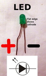
In another simple test to help find your way around an Arduino and its sketches, we can plug in an LED like the one pictured.
fuelquanledsymbol.jpg

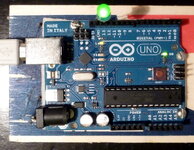
In this test, plug the short leg or cathode into the GND pin slot, slot #2 in the row along the edge of the Arduino nearest the LEDPin13 blinker. The long leg of the LED, the positive wire or anode, goes to LEDPin13. Now run the Blink sketch again to see the inserted LED blink.
fuelquanblinkon.jpg

There are hundreds of these trivial yet re-enforcing building-block exercises across the globe of the 'Net.

Using an Arduino to display Jeep gauge data is not much more difficult than the blink demonstration. You know that each gauge is fed by a sensor, a variable resistor that changes its resistance to the passage of electrical current depending on heat, or a fuel wiper level in the fuel tank along wound resistor, or even the pressure exerted by oil pressure. Each sensor has a ground, a variable resistance, and a power source. But Arduino reads voltage, not resistance or current. How to we change the circuit to show a voltage that varies when resistance changes?

That is pie-easy! We use two resistors, not just one, One of these resistors is the sensor resistor in usually our engine or fuel tank. The other we stick into the circuit to make a voltage-splitter.
fuelquanresistors.jpg

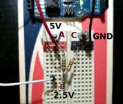
Here above is a representative voltage-splitter for demonstrating fuel level reading. Five volts from the Arduino 5V power pin plugs to A. Circuit ground plugs to C. We pick off the voltage in the middle of these two resistors at B, and expect the voltage at B to be half the total circuit voltage, since the resistors are identical and share equally the current that flows from A to C.

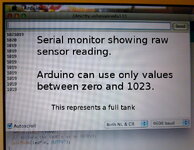
We've connected the pick-off point at B to Pin A0 on our Arduino. This is an analog pin, and only receives data, doesn't control anything. When we run a sketch to read data from A0 and display it on the Serial Monitor, we see the following:
fuelquanrawsensor600x465.jpg

But 1019 doesn't mean full tank to me; I want to have useful information, not just data from which I can't glean anything useful. If I subtract 1008 from each reading, I get 15, a number equivalent to the full tank I now have in my Jeep. If B to C was the variable wiper resistor in our fuel tanks, as the resistance drops between C and B, the voltage at pickoff point B would drop proportionately, and both our displayed number and the actual fuel remaining in the tank would drop. When we simulate this with a potentiometer, just another fancy name for a variable resistor, here are the numbers we would hope to see:

Fuel Quantity
15
Fuel Quantity
15
Fuel Quantity
15
Fuel Quantity
13
Fuel Quantity
10
Fuel Quantity
8
Fuel Quantity
6
Fuel Quantity
5
Fuel Quantity
4
Fuel Quantity
3
Fuel Quantity
2
Fuel Quantity
1
Fuel Quantity
0
Fuel Quantity
0

Here is the sketch that returned these data points:

/*
Arduino - AnalogInput
*/

int sensorPin = A0; // select the input pin for the potentiometer
int ledPin = 13; // select the pin for the LED
int sensorValue = 0; // variable to store the value coming from the sensor


void setup() {
Serial.begin(9600);
// declare the ledPin as an OUTPUT:
pinMode(ledPin, OUTPUT);
}

void loop() {
// read the value from the sensor:
sensorValue = analogRead(sensorPin);
// turn the ledPin on
digitalWrite(ledPin, HIGH);
// stop the program for <sensorValue> milliseconds:
delay(sensorValue);
// turn the ledPin off:
digitalWrite(ledPin, LOW);
// stop the program for for <sensorValue> milliseconds:
Serial.println("Fuel Quantity");
Serial.println(sensorValue-1008); //subtract this constant to get the number of gallons in my polyplastic 15Gal,
delay(sensorValue);
}

So far I've been displaying all data on the Serial Monitor. To get the 20X2 LCD to work, I must load the Liquid Crystal library. To do that, I download the liquidcrystal library, usually as a ZIP, from

Arduino Playground Download

I usually download to the Arduino Library and unzip it; On the Arduino IDE use these commands:

Sketch
Import Library
LiquidCrystal

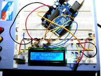
The wiring is a bit tricky the first time, but once any kinks are ironed out, here is what you should see:
fuelquanlcd600x450.jpg

And here is the Sketch that produces this display:

//FuelQuan15Gallons

#include <LiquidCrystal.h>

/*
Analog Input
Demonstrates analog input by reading an analog sensor on analog pin 0 and
turning on and off a light emitting diode(LED) connected to digital pin 13.
The amount of time the LED will be on and off depends on
the value obtained by analogRead().

The circuit:
If you've changed the pins, you'll want to make a handy table so you can update the sketch properly.
LCD pin name RS EN DB4 DB5 DB6 DB7
Arduino pin # 7 8 9 10 11 12

The circuit:
* LCD RS pin to digital pin 7
* LCD Enable pin to digital pin 8
* LCD D4 pin to digital pin 9
* LCD D5 pin to digital pin 10
* LCD D6 pin to digital pin 11
* LCD D7 pin to digital pin 12
* LCD R/W pin to ground
* 10K resistor:
* ends to +5V and ground
* wiper to LCD VO pin (pin 3)

* Note: because most Arduinos have a built-in LED attached
to pin 13 on the board, the LED is optional.


Created by David Cuartielles
modified 30 Aug 2011
By Tom Igoe

This example code is in the public domain.

Arduino - AnalogInput

*/
// initialize the library with the numbers of the interface pins
LiquidCrystal lcd(7, 8, 9, 10, 11, 12);
const int sensorPin = A0;
int ledPin = 13; // select the pin for the LED
int sensorValue = 0; // variable to store the value coming from the sensor


void setup() {
// set up the LCD's number of columns and rows:
lcd.begin(16, 2);
// Print a message to the LCD in the first row.
lcd.print("Fuel Quantity");
Serial.begin(9600);
// declare the ledPin as an OUTPUT:
pinMode(ledPin, OUTPUT);
}

void loop() {
// read the value from the sensor:
sensorValue = analogRead(sensorPin);
// turn the ledPin on
digitalWrite(ledPin, HIGH);
// stop the program for <sensorValue> milliseconds:
delay(sensorValue);
// turn the ledPin off:
digitalWrite(ledPin, LOW);
// stop the program for for <sensorValue> milliseconds:
Serial.println("Fuel Quantity"); //refresh the text in Row1 of the LCD
Serial.println(sensorValue-1008); //Adjust the sensor value to equal 15 Gallons
// set the cursor to column 0, line 1
// (note: line 1 is the second row, since counting begins with 0):
lcd.setCursor(0, 1);
// print the adjusted value for a full tank
lcd.print(sensorValue-1008);
lcd.println(" Gallons ");
delay(sensorValue);
}

If you've kept your place in the choir book as the pages were turned, you should in reading the above sketch see some old familiar friends.

We've gone from the very most basic function of the Arduino through LED hookup and voltage splitters. We've worked over a voltage splitter as a simulated fuel tank and gotten a sense of how we have to wire up our Arduino into the Jeep circuitry with an extra resistor to enable the Arduino to "see' the data we want. Lastly, the final hurdle of hooking up a 20X2 LCD and displaying lines of text and numbers has been touched on. The next step is to walk the entire shooting match out to my CJ7 , hook it up, and see what surprises the Real World has in store for us.
 
Re: Build a New Set of Gauges from Scratch - Experimenting

I need a 9 Volt power supply for the Arduino and 5 Volts to drive the OEM gauges; my intent is to see if I can get the TEMPERATURE GAUGE to read independent of the FUEL GAUGE that contains the power reduction circuit.

I've built two separate power supplies (PS), both quite simple. But then, so am I..... I hooked up the 5 volt PS to the keyed 12 volt line. The LED lighted, indicating that I'm producing 5 Volts. So I hooked 5 volts to the pin on the FUEL side (that space contains a TEMP gauge) with a shunt over to the 5V power in pin of the REAL temp gauge. There must be a short somewhere; the 5V PS went into thermal shutdown. So I cleverly removed the overheated PS from the circuit, and put in another. The LED lighted; every thing must be OK. Now to plug in the gauges...... THERMAL SHUTDOWN again. You'd think I could have learned.
5%20Volt%20Power%20Supply.JPG


3%20power%20circuit%20boards.JPG

Tomorrow I'll find the fault with my ohmmeter, isolate it, and re-try to run the temperature gauge without using the fuel gauge.

Meantime, I have found the right place on my dash for the Arduino LCD gauge, finalized the design to mount the LCD atop the Arduino Uno, and am fabricating a temporary mounting receiver out of wood from orange crates. The final will be stainless steel, once mounting spaces and the LCD fitting is complete.

This is taking longer than expected, but I am moving carefully to avoid mistakes. The other element is that every second week of May is a holiday for us Hunter-Gatherers. It is the peak if the annual dewberry (like blackberries but earlier, bigger, sweeter) crop.
Dewberry%20cobbler.png
 
Re: Build a New Set of Gauges from Scratch - Live Engine Run

This morning I disconnected the power shunt connecting the fuel gauge with the temperature gauge. I Ohmed all the connectors looking for a short to ground. Didn't find it immediately, so let sleeping dogs lie.

I rebuilt a 5V power supply with another scrap LM7805 Linear Voltage Regulator to test the temp gauge alone. This time the 5V supply didn't go to sleep.

5Volt%20power%20supply%20running%20off%20Jeep%20electrical%20system.jpg
The scrap LM7805 had a note on the back, my writing "gets hot!". Before the engine even got hot enough to move the temp gauge needle, I could tell my note to myself was accurate.... it was getting hot.

So I shut 'er down before I could let the smoke out of some of the parts. There is a 5V Linear Voltage Regulator by STMicroelectronics, #LD1085V50, DigiKey part number 497-3436-5-ND, that carry up to 3Amp continuous. They only cost a buck-seventy, and well worth it. I'll use the same circuit as with the 7805 devices, and never have to worry about it again!

Now it is time to bring out the Macbook and test the temperature circuit using the new temp sensor I bought last week. Remember that Arduino can't read ohms directly, so I hook up a voltage divider circuit, with one leg the temp sensor reading from 300 ohms cold down to the teens when the engine is very hot, and the other leg is a 180ohm resistor, somewhere near midrange of the temp sensor. Arduino supplies 5volts at one end of the voltage divider, and GND connects to the Jeep ground.
Receiving%20temp%20values%20engine%20running.jpg


Using this layout with values displayed on the Serial Monitor, I start off seeing 300 as a value after the engine has been run previously. In the six or seven minute engine run, the displayed numbers started dropping all the way down to 92 when I shut it down.

What does all this mean? It means the resistance decreases in the temp sensor as the engine gets hotter, the the resistance values we read from the temperature sensor leg of the voltage divider follow the engine heat cycle. It means that if we pick off the number when a temperature sensor is immersed in boiling water, which is 212F at sea level where I live, and another number when the temperature sensor is lying between two blocks of ice at 32 degrees F, we have the means to calibrate the temperatures across the full range of temp sensor engine readings. It means that once calibrated, those readings can be displayed on the Liquid Crystal Display (LCD) as accurate temperature displays of engine coolant with the same voltage divider setup as in the photograph above.

It also means that, since the fuel gauge operates like the temperature gauge only in a slightly different resistance band, we can again calibrate at full, mid-tank, and empty, alter the display software in the Arduino to accommodate the difference in resistance band from the temp gauge, and display fuel on the Arduino LCD.

The bottom line is that you don't have to buy replacements or step up to high-dollar gauges to have temperature and fuel displayed in your cockpit of your Jeep, any Jeep, not just CJ's. Not will you have to install a separate temp sensor.

I'd have to say that there is no killing hurry to hook the LCD into the circuit; that is proven hardware and technology. The next move is gonna be to O'Reilly's for another temp sensor, and do the calibration.

Unless my Hunter-Gatherer best friend from high school calls me to go out into the marsh to catch a boatload of Blue Crabs on Tuesday, I will report on calibration then.

Remember that we're Jeep people, and everything we do has to be water-tight. I'm using double heat-seal sleeves, marine grade glue, when I join two wires. I never want to have to do this work again. Actually that is nearly impossible anyhow; I won't live long enough to have the system fail.

Waterproof%20lead%20sleeves.jpg
.
 
Re: Build a New Set of Gauges from Scratch - Install Starts

22 May 2014 - Experiments over - install begins

A BRIEF RECAP

The sensors for fuel and temperature have been checked, and the temperature sensor was out of limits and had to be replaced for $7 bucks. Each input line to the cockpit has been hooked to the Arduino and the input values displayed on a breadboard layout wired just like the final product. Still unconclusive is the experiment of powering the temperature gauge from a 5 volt DC supply to run the gauge separated from the fuel gauge. It should work just fine, but the scrap 5V regulator, noted to run hot in previous experiments, did just that and the experiment interrupted. I am still of the opinion that the fuel gauge and the temperature gauges can operate indefinitely on power supplied from Jeep switched 12V down to 9V down to 5V. I will do just that, and report on how it went.

In planning the box to hold the Arduino and the 20X2 LCD display for fuel, temp, and possibly oil pressure, it occurred to me that as I always do everything the hard way (famous for that in my family), some people might want an easier route to the goal of digital electronic gauges. As a consequence, I abandoned my intended task of fabricating from a piece of single-side copper-clad PC board and a Sharpie black pen a printed circuit board to mount the LCD display. Instead, I have ordered a pre-manufactured kit that includes the PC board to piggy-back on the Arduino, all necessary parts to solder in (30 minute task), and instructions and tutorial to make it go. This cuts our job of hooking up nine Arduino pins correctly down to hooking up just two. The parts will arrive from Adafruit Industries tomorrow. [they arrived - 7PM UPS].

In addition, while scanning an electronics vendor for parts and ideas, several parts popped up that would allow anybody regardless of Jeep mechanical, programming, or electronic skill levels to add electronic gadgets to their Jeep for low bucks. These devices are:
Air Temp display (in Centigrade) for external temperature, carb intake temp, or any other temperature between -22 (O degrees C) and +158 (70C) Fahrenheit, but only displays in Centigrade. The cost is ten bucks and requires just DC power and GND. I have one for Outside Air Temperature; just looking for the right mounting spot for the sensor. The plus 158 Fahrenheit may not be high enough for the Gulf Coast in August!

A DC Volt Meter that hooks directly to the input and GND of our cockpit volt meters, and displays the output of the alternator.
LED%20Battery%20Meter%20Green.png


Turn Signal repeaters made of ten-segment LED bar displays about 1 inch long. I have one turn indicator that sometimes sticks, and the green point of light inside the speedo just doesn't get my attention often enough. I can add a couple of cheap Large Scale Integration (LSI) digital chips and have these 10-bar LED arrays do the "flashing arrow" dance from an imbedded position either atop, below, or imbedded in my dash board crash protector. One could also make a fuel gauge with one of these bars of LEDs for a display device rather than a meter or an Arduino-driven LCD. At two bucks a throw (try to find a beer on Friday night for 2 bucks at your local hangout) you can't go wrong.
10-bar%20LED%20Blue.png


A lot of us could benefit, with the cost of ethanol-free 89 octane at close to 4 dollars, with a panel-mounted vacuum gauge to maybe tone down our throttle foot. If we find the right sensor (transducer), a 24-LED bar readout would be fast enough to follow and display any excursion in engine throttle. The heart of such a device would be a Square Force-sensing Resistor, for 10 bucks. It will take a few engineering head-scratching sessions to get force and vector to give up a build model.
Bi-color%20Red-Green%2012%20LED%20pair.png


TODAY'S WORK
I had a stack of wood panels from a Christmas tangerine box, some epoxy and fiberglas cloth from boat-building. I figure three applications of epoxy to fill the weave of the cloth, some rattle-can RUSTOLEUM 2X undercoat, white, and maybe a rattle-can of stainless-steel paint for the finish. Yes, there really is such a paint style; here below is a part from my Dana 300 that turned out well and is still holding up. Once you clear-coat it, it looks half-decent.
D300%20T-Case%20cover%20painted%20Stainless%20Steel%204185.JPG


I use a plastic cup, a home=made mixing head head on a drill, and a cheap 1 inch paint brush to spread on epoxy. The stuff is pretty-much self-leveling, and finishes as slick as clear lacquer. New dash seal has just gone in, and I cut out part of the old one to seal the softtop above the windshield; I shouldn't take on any water so I'll only spray-paint the inside of the instrument mounting box for Gulf moisture.

epoxy1.jpg

epoxy2.jpg

epoxy3.jpg

epoxy6.jpg

The box I've built to house the Arduino gauge display and the Outside temp display is made from tangerine boxes and fiberglas. The fiberglas makes it almost as tough as aluminum, but will flex under extreme pressure without taking a set. Here are a few views of the instrument box being built.
woodbox2.JPG

woodbox3.JPG

I use wood dust (powdered wood) mixed with the epoxy to build up a filet at the seams. These will hold up pretty well.
woodbox6.JPG


It only took two coats of epoxy to fill the weave of the cloth, and I have only to rough up the surface of the cured epoxy to be sure the undercoat gets a good grip.

A WORD ABOUT ARDUINO AND SHIELDS

The term "shield" here is taken to mean a built-up circuit board that plugs directly into the Arduino pin rows so that circuit parts on the shield receive correct power and signals. This LCD shield kit is what came in tonight and will be soldered together tomorrow.
RGD%20LCD%20Shield%20Lit%20w%2016X2%20only%202%20pins.png


So tonight we leave it having cut out and prepared parts for the instrument mounting box, and glued up the side panels to the backplane. We've received the parts to build the LCD to plug atop the Arduino. Power supplies are ready. Tomorrow it is get the enclosure ready to fit and cut out apertures for the USB connector to the Arduino, figure out the placement of plastic standoffs and screw holes, and decide what else, aside from the outside temp display, would add safety or economy to our instrument display.
 
Re: Build a New Set of Gauges from Scratch - 2 FWD, i BACK

I spent the morning gluing a front panel on the instrument case (sounds so professional, what? What I mean is the tangerine crate wooden box), and putting together the LCD Shield to fit onto the Arduino. My expectations were, unfortunately, higher than the outcome. Oh, the shield works OK, but there are three observations than eliminate this hardware as a replacement instrument candidate. (1) Takes at least 2X the advertised 30 minutes unless you are doing your 21st one. (2) You need hands like a surgeon and eyes like Superman's X-ray vision to avoid trashing the tiny solder pads. (3) You are advised in the build instructions to grind off protruding legs of push-button switches and the potentiometer. When you do this, you wind up with copper filings all over and in your circuitry, and have a very real chance to cut a trace on the circuit board, accidentally.

Adding all of the above plus the difficulty now of getting to your plugin sockets on the Arduino, I have reached the conclusion that, for you and I, more comfortable with SawzAlls, BFHs, and big sockets with cheater-bars on them, direct hard-wiring is the way to go. I' working on a diagram so I don't make any more mistakes than usual. I'll put it up here next report.

If you've hung with me this long, you deserve a reward. Here is my Cousin's engine, LS 5.7L 430 HP, going into his 1940 Ford PU. Too much for my AMC20 rear end, I am sure.
LS%205.7L%20430HP.jpg

LSS%205.7L%20430HP%20in%201940%20Ford%20PU.JPG
 
Re: Build a New Set of Gauges from Scratch - Hooking up

After quite a lot of experimentation, it is time to hook everything up. The work left to do is cut openings and mount parts in the box, mount the box on the dash with an access port cut for wire passage, hook up wires between the liquid crystal display and the arduino computer, and hook up/calibrate the fuel remaining wire from the fuel tank float, and the temperature sensor wire from the new temp sensor thyristor that replaced the old one, proven badly out of tolerance.

Mounting the parts into the box is easy of you are careful:
Inletted1.JPG

Inletted2.JPG

Inletted3.JPG


My intent is to install a voltmeter readout and an Outside Air Temperature (OAT) readout as well as the other engine monitor gauges. I have one of the two, the OAT gauge, and will mount it here:
Front%20Panel.JPG


The Arduino goes onto the back panel with plastic standoffs:
Arduino%20installed.JPG

Arduino%20in%20the%20box2.JPG

Arduino%20in%20the%20box1.JPG


Now begins the wiring together of the components. I need a PC board to hold the LCD, the input connectors for fuel level sensing, temperature sensing, oil pressure sensing, voltage sensing, and a couple of three-connector screw-clamp wire connectors for the future temperature sensors that will be independent of installed OEM devices. I have the main connector, a piece of multistrand flat cable from my junk box:
multistrand%20cable.JPG


Now it is back to the Sharpie pen, the Dremmel wire insert hole drill, and the pencil soldering iron to get it all connected. More about that when the next task is finished.

"Life Is Good" say all the spare covers on backs of Jeeps. Today remember those to whom life was just as good, but who gave up their lives or body parts in the continuous struggle to keep the rest of us free to build and drive our Jeeps.
 
Re: Build a New Set of Gauges from Scratch - Final Countdown

Here is the short list of things left to be done:

Check display PC board and wiring for shorts.
Cut out wiring access port in dash. Position box and drill/tap mounting screw holes.
Mount Arduino in box with display and plug in wiring.
Test LCD Display and backlighting under power.
Mount wire clamps and resistors for voltage splitters onto mini-breadboard.
Plug in wires from fuel float, temperature sensor into mini-breadboard and Arduino.
Test each circuit one at the time for proper interaction with the LCD display.
Combine testing software into one program and load to Arduino. Run around in the Jeep testing the output.

Final steps:
Locate the oil pressure sensor output and wire it into Arduino.
Integrate oil pressure display.
Calibrate temperature sensor in ice water and in boiling water with analog thermometer and
cooking digital thermometer.
Run the Jeep until the tank is dry to test fuel level software.
Button it all up.

To recap, there are four parts to a digital electronic Jeep Gauge display. One is a pre-built Arduino microcomputer. Connected to the Arduino by wires is a breadboard holding screw clamps for the connections from Jeep sensors; temperature, fuel level, oil pressure. Also connected to the Arduino by wires is a liquid crystal display (LCD) showing 16 characters, white on blue, on each of two lines. The last component is a stable 5V and 9V source of power. The first three are mounted inside a box that will fasten to the dash. The power supply will mount on the back side of the dash.

The 16X2 LCD has been wired on a cobbled-together PC board. From the back, you see this:
LCD%20display%20back.JPG

The small slotted dingus on the lower left is a variable resistor to adjust contrast so the characters stand out clearly.

From the front,
LCD%20display%20front.JPG

Before applying power (5V DC), all connections must be probed with an ohm meter to detect any shorts. There were none. With that safety check, we can apply power. This checks the LED-illuminated backlight, and the variable resistor that adjusts contrast. If these work, we're pretty much home free.
power-up%20test.JPG

And the power test is successful!

The attachment of Jeep engine sensors is pretty simple. Usually the drill is to apply power to a voltage splitter and pick off the voltage from a wire into the Arduino. The sensor circuits all ground to vehicle common.

Here is a playing-card-sized breadboard that is small enough to fit into the dashboard display box. It is just a bunch of holes with solder pads on the back.
External%20connector%20bare%20board.JPG

Each long border has two runs down for power attachment. Each set of five holes running across the card in two ranks are all connected, so we can make five easy connections to form a circuit node. If we were to need more, jumpers will get us as many connections as we could want. But that is overkill. Our needs are simple. For each Jeep engine sensor, we'll need power, a voltage splitter resistor, and a pickoff attachment for the wire feeding one input connector on the Arduino. For future needs, I've placed three three-post screw-clamp connectors down the middle. These connectors will serve any sensors that will be independent of the Jeep grounding system; just power, ground, a voltage splitter resistor and a pick-off wire.
External%20connector%20breadboard%202.JPG


The next important step is to plug into the Arduino with the output wiring that decodes into characters for the display. It is simple; bare tinned wires, but plugged into the correct Arduino slots.
LCD%20Hookup%20wires.JPG

With six of them, can't be too hard! I'll make the hookup and begin the test of the Arduino-LCD Display pair with no sensor in the loop tomorrow.
 
Re: Build a New Set of Gauges from Scratch - Piece by Piece

The LCD display in the box has been "burning in", an electronic term for operating under power for a long period to see if we can get smoke to come out. It has been on for 48 hours with no cause for concern; but earlier there was serious concern!

You saw from last post the rat's nest of wires inside the box. As I was running both the OAT display and the LCD on battery AND USB, I disconnected the battery (Arduino runs OK on LCD at light load) and moved a wire or two, measuring the proposed location of the hookup panel.
Fuel%20remaining.jpg

When I looked back at the display, the text was all hieroglyphics. I just KNEW I'd shorted two wires together.

To make the story short, wasn't the cause at all. The OAT display draws enough power to cause the Arduino, on USB power alone, to garble the text output to the LCD panel. This I learned purely by accident after a full two hours of ohm'ing the wire connections. But I learned!

Here is something else I learned that, should you take this route to make some electronic changes to your Jeep, will save you much time and trouble. I am so used to grabbing a wire stripper, stripping the ends, tinning with a solder iron then making the needed mechanical connection that I don't give it a second thought. But today, just today, I realized that I have a stockpile of wires cut, "stripped and tinned", in the form of store-bought jumper cables, and they come in all colors.
Jumpers1.jpg

Jumpers2.jpg


After this revelation, work went ahead swiftly. I now have everything built and am ready for an end-to-end power-on test.

First, a 9V 1.5AMP power supply for the Arduino and for the 5V 3AMP supply
5Volt%20board%20front.jpg

5Volt%20board%20back.jpg


that will power the OAT display and the engine sensors through the sensor connector board, below.
Sensor%20board%20front.jpg

Sensor%20board%20back.jpg

The sensor connector board has places for six devices to be attached; three 3-wire sensors independent of the Jeep engine system, and three for the fuel level, engine temperature, and oil pressure that are built-ins. The first two have never worked and from reading Jeep-CJ Forums are a continuous headache for almost all CJ owners.

Now that it has stopped raining for the first time in seven days, I can get the Jeep out of the garage, run the full system power test, and begin to mount and hook up the 9V power, 5V power, and the box holding the Arduino, the LCD, and the sensor connector board, along with the OAT display. That is what I am out the door right now to begin.
 
Re: Build a New Set of Gauges from Scratch - All Ahead Slow

Power check is complete; the 9-volt board and the 5-volt board both output the voltage they're supposed to, and the voltage regulators don't get hot. The most tedious job was wiring the sensor connector board.
sensor%20hookup%20board.JPG


There are three connectors for engine-installed sensors, and three for three-wire independent sensors. Let's deal with the 3-wire sensor connectors first.
DS18B20%20wire%20with%204.7K%20pullup%20resistor.JPG

This cable with a DS18B20 digital temperature sensor has the conventional power and ground wires, and the yellow is the data delivery wire. To condition the signal for the Arduino's use, a 4.7K resistor hooks between 5V POWER across to yellow DATA. The power runs are on the outer edges of the sensor connect board, along with the ground trace. All I needed to do was hook the triple-screw-type connector to PWR and GND, jump to the DATA pin with the 4.7K resistor. The one extra wire to be connected to DATA goes to one of the digital input pins on the Arduino.
Sensor%20hookup%20board%20for%203-wire.JPG


The two-post screw-down connectors will take in the sensed voltage from a voltage divider made up of 5Volt DC feeding a 1K Ohm resistor. The other end of the 1K resistor joins a 3-way connector with the engine sensor input and the analog input pin selected on the Arduino. I put in plugin points instead of hard soldering for the two resistor ends so that I can change them as I tune the system for accurate representation.

These screw-clamp connectors feed data to the Arduino through a cable set, six wires, one for each connector on the sensor board. The cable set plugs into Arduino pins A0 through A5. Here below are the header pins being soldered onto the Arduino pin set:
Header%20wiring%20soldering%20closeup.JPG


How it plugs to the Arduino is pretty simple:

Hookup%20wires%20header%20flash.JPG


There wires are just jumper wires bought for use in breadboarding new hardware. They are just what the Doctor ordered for our needs, and don't require a lot of extra work.

This afternoon I mounted the sensor connector board inside the wooden box with the Arduino and the independent Centigrade temperature readout. I cut a 1.5 inch circular cable access port into the back of the box.... don't have a photo of that yet. The next move is to mount the box on the dash where I must cut a mating wire access hole. I'm waiting for my Number2 Son and his wife to arrive, sometime in the next 15 minutes, to show them the work, and will draft them into helping me. Many Hands Make Light Work!

Sensors%20to%20Arduino%20input%20pins.JPG
 
Re: Build a New Set of Gauges from Scratch - END GAME!

Today I got to look at the fuel quantity remaining for the first time since I bought this '80 CJ7 in Nov. 2009! What a pleasure.... I suffer from fuel anxiety, a holdover from years of flying jet fighters with "short fuel legs". But that's all over now.
16JunPic07.jpg


The quantity shown seems pretty close to reality.... my son and daughter-in-law were out with me running trails in Desoto National Forest all of the week before.

16JunPic.jpg


To get to this milestone, I cut a wire passage in the dash, tapped some screw holes to mount the wooden box with the electronics, and did a burn-in of the full system for about an hour. Nothing got hot to the touch, and no smoke!
16JunPic01.jpg

16JunPic02.jpg

16JunPic03.jpg

16JunPic04.jpg

16JunPic05.jpg

16JunPic06.jpg

16JunPic00.jpg


When the full burn-in time was over with no faults, I hooked an Apple MacBook up to the Arduino and loaded a program that only looked at the fuel sensor. I have the temp and oil pressure sensors connected, as well as an engine coolant temp probe to calibrate the engine-mounted temperature sensor, and a temperature probe for engine intake air temp. I'll get to those one at a time.

Getting the fuel quantity was easy. I have a 1,000 ohm (1K) resistor hooked to 5VDC, and next connected to the pink wire terminator that runs to the fuel tank float resistor. I connect Arduino PinA0, an analog input port, to the junction of the 1K resistor and the fuel pink wire.
The Arduino "analogread(A0)" command returns an integer 'fuelValue' between 0 and 1023. You can't get much sense from that until you "MAP" the returned value onto the range of the capacity of the fuel tank:

fuelValue - map(fuelValue, 0, 1023, 0, 15);

So now the content of 'fuelValue' is somewhere between 0 and 15, which we hope is the minimum and maximum we could ever see filling our fuel tank. How hard is that?

Tomorrow I'll fill the tank, check to see how close to 15 gallons the gauge reads, and begin the burn-down to empty to see how close to zero the gauge reads when the tank is empty.

I'm not going to like doing that.... fuel anxieties again!
 

Jeep-CJ Donation Drive

Help support Jeep-CJ.com by making a contribution.

Help support Jeep-CJ.com by making a contribution.
Goal
$200.00
Earned
$25.00
This donation drive ends in
Back
Top Bottom