Electric Fan Wiring assistance needed.
-
Hello Guest, we are proud to now have our Wiki online that is completely compiled and written by our members. Feel free to browse our Jeep-CJ Wiki or click on any orange keyword when looking at posts in the forum.
You are using an out of date browser. It may not display this or other websites correctly.
You should upgrade or use an alternative browser.
You should upgrade or use an alternative browser.
Electric Fan Wiring assistance needed.
- Thread starter BrockGrimes
- Start date Start date:
- Last post Last post:
Electric Fan Wiring assistance needed.
harleydragon
Senior Jeeper
- Posts
- 503
- Media
- 4
- Thanks
- 1
- Location
- South Georgia
- Vehicle(s)
- 80 cj7 w/ not even stock 350,350 turbo tranny,208 t-case,dana 60 front,14 bolt rear..nothing on this jeep is stock..
80 cj7 w/nearly stock 350,350 turbo tranny,divorced 68 gmc t-case and dana 44 front,12 bolt rear...
91 jeep yj wrangler w/4.0,auto,stock axles,soa
looks good..I would probably put the light on the other side of the manual override switch..where it is now the light would be on even if the switch was turned off
IOPort51
NOT the voice of reason Jeep-CJ.com
- Posts
- 13,956
- Featured
- 5
- Media
- 458
- Thanks
- 12
- Location
- Garland Texas
- Vehicle(s)
- 1977 cj-5
4.2 W/MC2100 carb, 4.0 head W/3 angle valves,SS Header,TFI ignition with MSB-6 offroad module,CS144 140 amp RPS alternator with remote regulator T-150,d-20,Dana 44 with OX lock and disk brakes. D-30 with Spartin locker,
skyjacker 2.5 lift?nitro shocks,31" BFG A/T off road.8000 lb Warn winch, original owner.=^)
2006 Toyota Tacoma
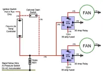
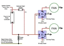
I am afraid that the second motor circuit does not work for me. It looks to be energizing the 2nd motor through the coils of the relays rather than the contact. Way too much current to pull this off for very long.
Needs a temperature switch to ground the relay coils, where the light is now. as manual switches go I think the only reason to turn it off is a water crossing and if I go in that deep I do not think the fan will run for long when the redeator hits the cool water, just saying.
This next part is kind of hard to follow, not sure I follow it myself but here goes.
The horizontal line from the 2nd motor and the line between the 1st motor and term 87 should go to the line to the 2nd motor and the line from that point to the indicator light line should go away. As is the contacts form both relays are both powering the 1st motor and the current drawn by the second motor is passing through the coil which only has 18 ga wire and is not made to carry 9 or 10 amps plus end rush.
Bosh 40amp relay sockets are wired with 14 ga wire, which will carry 40 amps 12V dc. which is actually a little more than the relay contacts are rated for.
the coil wire is 18 ga, I think. and don't forget the fuzes on the line power from the battery as close to the battery as possible so it protects as much wire as possible. 15, maybe 20amps those fans should not draw more than 9 or 10 amps dc.
Automatic reset circuit beakers are totally off the hook.
Let me know if you need supplier sites for relays and everything but Waytec should be able to cover what ever you need.
I thought you did this already.


these handle two fans, high and low beam and aux lights and the horn.
Needs a temperature switch to ground the relay coils, where the light is now. as manual switches go I think the only reason to turn it off is a water crossing and if I go in that deep I do not think the fan will run for long when the redeator hits the cool water, just saying.
This next part is kind of hard to follow, not sure I follow it myself but here goes.
The horizontal line from the 2nd motor and the line between the 1st motor and term 87 should go to the line to the 2nd motor and the line from that point to the indicator light line should go away. As is the contacts form both relays are both powering the 1st motor and the current drawn by the second motor is passing through the coil which only has 18 ga wire and is not made to carry 9 or 10 amps plus end rush.
Bosh 40amp relay sockets are wired with 14 ga wire, which will carry 40 amps 12V dc. which is actually a little more than the relay contacts are rated for.
the coil wire is 18 ga, I think. and don't forget the fuzes on the line power from the battery as close to the battery as possible so it protects as much wire as possible. 15, maybe 20amps those fans should not draw more than 9 or 10 amps dc.
Automatic reset circuit beakers are totally off the hook.
Let me know if you need supplier sites for relays and everything but Waytec should be able to cover what ever you need.
I thought you did this already.


these handle two fans, high and low beam and aux lights and the horn.
harleydragon
Senior Jeeper
- Posts
- 503
- Media
- 4
- Thanks
- 1
- Location
- South Georgia
- Vehicle(s)
- 80 cj7 w/ not even stock 350,350 turbo tranny,208 t-case,dana 60 front,14 bolt rear..nothing on this jeep is stock..
80 cj7 w/nearly stock 350,350 turbo tranny,divorced 68 gmc t-case and dana 44 front,12 bolt rear...
91 jeep yj wrangler w/4.0,auto,stock axles,soa
I read the diagram as only having 1 fan with 2 relays wired in parrallel in case one of them went out and the other large circle being a toggle switch to manually turn it off when desired..if that is correct then it will work..You could add a thermostat controlled switch if desired..I would add it in series with the toggle switch and then parrallel another toggle switch with the thermal switch in case you wanted/needed to bypass it..
Last edited:
IOPort51
NOT the voice of reason Jeep-CJ.com
- Posts
- 13,956
- Featured
- 5
- Media
- 458
- Thanks
- 12
- Location
- Garland Texas
- Vehicle(s)
- 1977 cj-5
4.2 W/MC2100 carb, 4.0 head W/3 angle valves,SS Header,TFI ignition with MSB-6 offroad module,CS144 140 amp RPS alternator with remote regulator T-150,d-20,Dana 44 with OX lock and disk brakes. D-30 with Spartin locker,
skyjacker 2.5 lift?nitro shocks,31" BFG A/T off road.8000 lb Warn winch, original owner.=^)
2006 Toyota Tacoma
Pete I thought you were going to use the Toyota two fan set up. the Concourse?
IOPort51
NOT the voice of reason Jeep-CJ.com
- Posts
- 13,956
- Featured
- 5
- Media
- 458
- Thanks
- 12
- Location
- Garland Texas
- Vehicle(s)
- 1977 cj-5
4.2 W/MC2100 carb, 4.0 head W/3 angle valves,SS Header,TFI ignition with MSB-6 offroad module,CS144 140 amp RPS alternator with remote regulator T-150,d-20,Dana 44 with OX lock and disk brakes. D-30 with Spartin locker,
skyjacker 2.5 lift?nitro shocks,31" BFG A/T off road.8000 lb Warn winch, original owner.=^)
2006 Toyota Tacoma
This is the best information on Bosh relays I have seen. You can do a lot of cool things with Bosh relays. I am tempted by the "flash headlights left and right". I am sure that would be all sorts of fun.
http://dlcparts.com/images/BoschGuide.pdf
http://dlcparts.com/images/BoschGuide.pdf
ThisGuyUKnow
Full Time Jeeper
- Posts
- 2,785
- Featured
- 2
- Thanks
- 1
- Location
- Harleysville, PA
- Vehicle(s)
- 1986 CJ7 Laredo 4.0,Nv3550,D300 Twin Stick,AMC20 3.31, 31 BFG
Honda vtx1800c
I see several issues looking at your schematic.
My first an largest question for you is why two relays? Looking at how you have them wired everything on those relays are the same electric point. If you were to wire it up according to your schematic and then unplugged either out you would still have a functioning circuit. Is this in case one burns out? I guess in theory you are splitting the amperage draw half between the two relays which would reduce the chance of burning one out but I have a 30 amp fuse on my F150 and both fans run off it and it has never blown the fuse and most relays are rated at 40 amps. What I would do is but a 25-30 amp fuse instead of using fusable link
My second observation is your "ign on source" You indicate you prefer this to the acc source so that it wont run in acc. On the cj wiring these are one and the same. so in your wiring diagram this setup will turn on the fan as soon as you turn the key even if you dont hit the starter unless you have your manual switch off.
Third, as stated by another member your indicator light needs to be moved to between the override and the ground so that it will turn off when you deactivate the fan.
Finally, The activation source is constant in this diagram... You really need to add a switch that is activated by a thermostat. You don't want the fan kicking on till your thermostat opens up and hot coolant starts flowing through the radiator.
I suggest that you just buy a fan controller from the autoparts store. THey are universal and run about 20-50 bucks. I strongly suggest you look at the flexalite variable speed controller which runs 90-120 dollars depending on where you get it. It is easy to wire, has a computer that controls how much amperage the fans draw depending on the temp of the engine, it has the provisions for an indicator light, as well as provisions for a manual shutoff. I use this one in all my electric fan conversions (except with my current cj because the fans are controlled by the ecms).
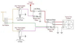
I edited your schematic in paint to move the indicator light and also show the circuit with the second relay deleted.
Last edited:
Jimbos76cj
Full Time Jeeper
- Posts
- 2,223
- Thanks
- 1
- Location
- St.Cloud FL
- Vehicle(s)
- 83 CJ-7.. 4" YJ springs front rear, J-10 44 front/AMC 20 rear,6 cy auto dana 300 35' bfg Done and gone!!
Ask me about my head light upgrade harness!!!
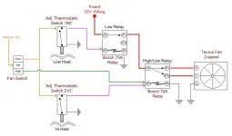
I picked up a 80ish amp constant duty solenoid for my contour fan. I wired it with 10 gauge wire. I run the ground for the relay to a 185 degree on coolant switch. The ground wire goes from the switch to my manual shut off switch (mounted upside down in my dash so switch down is on) then out to my relay ground. By doing it this way the motor is allowed to heat up to operating temp. Once it hits the 185 the switch ground out the relay allowing it to close and turn the fan on. If I need to shut the fan off to play in the water I flip my manual over ride switch to the up position and and it breaks the ground turning the fan off.
And like stated earlier your light is wired wrong. it should be wired to one side of the switch or the other. if you want to wire to the side that has power to it thats fine but dont ground it. power should go into the light then out to the switch. I would wire it on the ground side. Ground in then on terminal then out to the ground source.
And like stated earlier your light is wired wrong. it should be wired to one side of the switch or the other. if you want to wire to the side that has power to it thats fine but dont ground it. power should go into the light then out to the switch. I would wire it on the ground side. Ground in then on terminal then out to the ground source.
Jimbos76cj
Full Time Jeeper
- Posts
- 2,223
- Thanks
- 1
- Location
- St.Cloud FL
- Vehicle(s)
- 83 CJ-7.. 4" YJ springs front rear, J-10 44 front/AMC 20 rear,6 cy auto dana 300 35' bfg Done and gone!!
Ask me about my head light upgrade harness!!!
70-111224 - White Rodgers 70-111224 - Solenoid, SPNO, 12 VDC Isolated Coil, Continuous Duty
link for solenoid. May it be bigger then needed? probaly but after reading the post on people who's 30-40 amp relays burnt up on trails I decided it wouldnt hurt.
link for solenoid. May it be bigger then needed? probaly but after reading the post on people who's 30-40 amp relays burnt up on trails I decided it wouldnt hurt.
harleydragon
Senior Jeeper
- Posts
- 503
- Media
- 4
- Thanks
- 1
- Location
- South Georgia
- Vehicle(s)
- 80 cj7 w/ not even stock 350,350 turbo tranny,208 t-case,dana 60 front,14 bolt rear..nothing on this jeep is stock..
80 cj7 w/nearly stock 350,350 turbo tranny,divorced 68 gmc t-case and dana 44 front,12 bolt rear...
91 jeep yj wrangler w/4.0,auto,stock axles,soa
I believe that the 2 relays is just a safety feature in case one fails..I don't use 2 on mine but there is no harm in it.
IOPort51
NOT the voice of reason Jeep-CJ.com
- Posts
- 13,956
- Featured
- 5
- Media
- 458
- Thanks
- 12
- Location
- Garland Texas
- Vehicle(s)
- 1977 cj-5
4.2 W/MC2100 carb, 4.0 head W/3 angle valves,SS Header,TFI ignition with MSB-6 offroad module,CS144 140 amp RPS alternator with remote regulator T-150,d-20,Dana 44 with OX lock and disk brakes. D-30 with Spartin locker,
skyjacker 2.5 lift?nitro shocks,31" BFG A/T off road.8000 lb Warn winch, original owner.=^)
2006 Toyota Tacoma
ThisGuyUKnow
Full Time Jeeper
- Posts
- 2,785
- Featured
- 2
- Thanks
- 1
- Location
- Harleysville, PA
- Vehicle(s)
- 1986 CJ7 Laredo 4.0,Nv3550,D300 Twin Stick,AMC20 3.31, 31 BFG
Honda vtx1800c
And like stated earlier your light is wired wrong. it should be wired to one side of the switch or the other. if you want to wire to the side that has power to it thats fine but dont ground it. power should go into the light then out to the switch. I would wire it on the ground side. Ground in then on terminal then out to the ground source.
Doing it that way, if the bulb burned out it would stop the operation of the fan. Also the entire amperage load would then be pushed through the light as well.
harleydragon
Senior Jeeper
- Posts
- 503
- Media
- 4
- Thanks
- 1
- Location
- South Georgia
- Vehicle(s)
- 80 cj7 w/ not even stock 350,350 turbo tranny,208 t-case,dana 60 front,14 bolt rear..nothing on this jeep is stock..
80 cj7 w/nearly stock 350,350 turbo tranny,divorced 68 gmc t-case and dana 44 front,12 bolt rear...
91 jeep yj wrangler w/4.0,auto,stock axles,soa
Doing it that way, if the bulb burned out it would stop the operation of the fan. Also the entire amperage load would then be pushed through the light as well.
exactly..the indicator light should not be wired in series with the circuit..it should be wired in parallel, after the switch,with it's own ground
ThisGuyUKnow
Full Time Jeeper
- Posts
- 2,785
- Featured
- 2
- Thanks
- 1
- Location
- Harleysville, PA
- Vehicle(s)
- 1986 CJ7 Laredo 4.0,Nv3550,D300 Twin Stick,AMC20 3.31, 31 BFG
Honda vtx1800c
I believe that the 2 relays is just a safety feature in case one fails..I don't use 2 on mine but there is no harm in it.
No there is no harm in it but I believe it is best to apply KISS when doing DIY wiring. The liklihood the relay will burn out is low if you use a quality relay rated for 30 AMPS or more. You don't want the relay to be the weak point in the system that is what fuses or fusable link is for.
IOPort51
NOT the voice of reason Jeep-CJ.com
- Posts
- 13,956
- Featured
- 5
- Media
- 458
- Thanks
- 12
- Location
- Garland Texas
- Vehicle(s)
- 1977 cj-5
4.2 W/MC2100 carb, 4.0 head W/3 angle valves,SS Header,TFI ignition with MSB-6 offroad module,CS144 140 amp RPS alternator with remote regulator T-150,d-20,Dana 44 with OX lock and disk brakes. D-30 with Spartin locker,
skyjacker 2.5 lift?nitro shocks,31" BFG A/T off road.8000 lb Warn winch, original owner.=^)
2006 Toyota Tacoma
ThisGuyUKnow
Full Time Jeeper
- Posts
- 2,785
- Featured
- 2
- Thanks
- 1
- Location
- Harleysville, PA
- Vehicle(s)
- 1986 CJ7 Laredo 4.0,Nv3550,D300 Twin Stick,AMC20 3.31, 31 BFG
Honda vtx1800c
I definitely think variable speed controllers are the way to go with the electric fans. I use it in every fan conversion i do. I currently have one on my dual windstar fan coversion in my 06 F150. Ihttp://www.summitracing.com/parts/flx-33054/overview/
IOPort51
NOT the voice of reason Jeep-CJ.com
- Posts
- 13,956
- Featured
- 5
- Media
- 458
- Thanks
- 12
- Location
- Garland Texas
- Vehicle(s)
- 1977 cj-5
4.2 W/MC2100 carb, 4.0 head W/3 angle valves,SS Header,TFI ignition with MSB-6 offroad module,CS144 140 amp RPS alternator with remote regulator T-150,d-20,Dana 44 with OX lock and disk brakes. D-30 with Spartin locker,
skyjacker 2.5 lift?nitro shocks,31" BFG A/T off road.8000 lb Warn winch, original owner.=^)
2006 Toyota Tacoma
please tell us where a temperature activated variable speed motor controller can be found.

ThisGuyUKnow
Full Time Jeeper
- Posts
- 2,785
- Featured
- 2
- Thanks
- 1
- Location
- Harleysville, PA
- Vehicle(s)
- 1986 CJ7 Laredo 4.0,Nv3550,D300 Twin Stick,AMC20 3.31, 31 BFG
Honda vtx1800c
please tell us where a temperature activated variable speed motor controller can be found.
I dont know about a variable speed motor, but I linked the controller in my last post. If achieves differenct fan speeds by limiting the amount of amps the motor(s) are pulling starts at about 60% at the low temperature and up to 100% if the temp continues to rise. I rarely see it run longer than a a minute even in heavy traffic on my 5.4
Jimbos76cj
Full Time Jeeper
- Posts
- 2,223
- Thanks
- 1
- Location
- St.Cloud FL
- Vehicle(s)
- 83 CJ-7.. 4" YJ springs front rear, J-10 44 front/AMC 20 rear,6 cy auto dana 300 35' bfg Done and gone!!
Ask me about my head light upgrade harness!!!
exactly..the indicator light should not be wired in series with the circuit..it should be wired in parallel, after the switch,with it's own ground
Doing it that way, if the bulb burned out it would stop the operation of the fan. Also the entire amperage load would then be pushed through the light as well.
Hmmm .. Guess I got a new task ahead of me.. Little bit of rewiring for some bulbs. Thanks for the correction
Jeep-CJ Donation Drive
Help support Jeep-CJ.com by making a contribution.
Help support Jeep-CJ.com by making a contribution.
Goal
$200.00
Earned
$0.00
This donation drive ends in
0 hours,
0 minutes,
0 seconds
0.0%


