• To celebrate the 4th of July, starting today (07/01/2025) all User Upgrades will be reduced by 10% (thru 07/08/2025) To use this special coupon use the code 2025-4th-10percent at check out. If you are already a supporter your existing package will be extended.
    Thank you for your support!
  • Hello Guest, we are proud to now have our Wiki online that is completely compiled and written by our members. Feel free to browse our Jeep-CJ Wiki or click on any orange keyword when looking at posts in the forum.

Purpose of resistance wire

Purpose of resistance wire

yellow85cj

Senior Jeeper
Posts
672
Media
3
Resources
1
Solutions
3
Thanks
32
Location
Ft Worth,TX
Vehicle(s)
85 CJ7, 258,4.0 head, T177, D300, Dana 30, AMC 20, 3.54
Trying to figure out the wiring differences between an 85 AMC 150 and the AMC 258 i6 / 4.2l . One of the problems is a resistance wire(s).

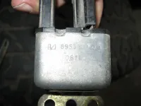
This started with the choke/manifold heater wiring. The 4cyl for some reason has a separate choke relay. Little metal box that was bolted to the PS fender.
IMG_3007_zpsdcu4rd8x.webp
Now the relay is fed directly from the alternator. On a AMC 258 i6 / 4.2l this wire is spliced into coil/ignition module feed.

On the 4 cyl there is a resistance wire, from the same alt connector that the above wire is. It is spliced into the coil/ignition module feed.

Since the AMC 150 is basically a AMC 258 i6 / 4.2l with 2 cyl cut off, and the ignition module and coil are the same for both, why does one need a resistance wire and the other not?

On both, they are part of the ignition feed 10ga wire coming from the fuse block.

Ok, pretty much understand that I need to dump the resistance wire and do a little splicing to get to match the 6 drawings. But why is the resistance wire there in the first place? Why two different resistance rated wires feeding the same thing?

Does the 6 cyl alt connector have 2 wires coming from it, or just one? (don't have a 6 to look at, so a pic from one would be nice)

Have I just not found the resistance wire on the 6 cyl drawings?

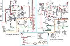
4cyl%206%20cyl%20resistance%20wire_zpsn2dqaicb.webp

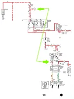
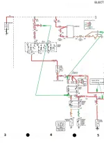
BTW, I took the 84-86 FSM schematics and colored them in, along with an 83 version (easier to get an overall picture than the 84-86 drawings).

They are on Dropbox. When you open the file ther is a box in the top right hand corner with 3 "dots". Click on this and a menu comes down that will allow you to down load the file. There is a .jpeg file and a .png file (MS Paint) in case you want to make changes in paint.

84-86
https://www.dropbox.com/sh/gyg0lqi7gjkc5ja/AAALL3yDKB1X0AlsVMn_rcQ8a?dl=0
83 overall
https://www.dropbox.com/sh/4nbko8o5nqiwak0/AAA9ctAXSBIuNp06vDGK1SAFa?dl=0
Fuse box Cavity Chart
https://www.dropbox.com/sh/b5od1zm28w4ttvv/AAC8hnM6wA4__SQiA42GA_0Ia?dl=0
 
On my AMC 258 i6 / 4.2l , there is a resistance wire from the #1 post on the alternator that feeds into the ignition module, coil, and ignition switch. From what I understand this cuts down the voltage into the ignition module as a operating voltage of 14.5 will fry it. this wire can be purchased from NAPA as p/n ICR22. Looking around the net, I really can't find much about it. Sometime in the last century I did cut some from that long resistance wire and it now feeds 9 volts under operation and I have had no issues from it. I also would like to know more of particular wire and its purpose.
 
The resistance wire for the coil is in the loom against the firewall.
You want full 12+ coil voltage when starting due to starter drainage of the battery.
Continuous voltage above 9vdc will fry the coil. After the engine starts and the ign is in the run circuit. It's feed the 9vdc via the res. wire.

Is this 4cly a CA. model or 49 state?
LG
 
Just to expand on what others have said. Coils are designed to step up battery voltage at higher speeds. On the other hand, and by design, the coil would produce too much voltage at low speeds overheating of the coil, or points depending on the ignition system.

The ballast resister is heat sensitive, higher heat at low speeds (less flow) and lower heat at high speeds (higher flow). I believe the wire resister is regulated by length. Without a resister you would cook the points in a ignition points setup, and you would cook the coil in a electronic ignition.
 
Torxhead - so both wires in the drawing, even though drawn differently -one straight line, one "squiggly" are both resistance wires?

That's where I start to get confused. In the drawing the "straight" brown wire feeds (used as the trigger wire) the choke relay. And it is just a plain old copper wire, not "silver" as the other brown wire coming from the same alternator connector. The resistance wire (squiggly) that comes from the alt is a single strand of "silver" (some type of alloy I guess). Why would a lower voltage (resistance wire) be needed. Why not just 12v as with all the other relays?

And there is a resistor wire (also silver but multi stranded) spliced into the 10ga ignition feed that runs to the coil and ignition module.

So there are 2 (as per the FSM drawings) resistance wires spliced at the same point into the ignition feed wires? I don't understand.

Lumpy Grits - Don't think it is a CA CJ. Only way I have been able to ID a CA CJ is that the AMC 258 i6 / 4.2l is serp belt not V-belt. Bought it in FL in 02. Haven't seen anything that would ID it as a CA CJ.

There is a resistance wire, kinda red with trace that is shown in the drawings that feeds the coil and ignition module. Question is, why on the 4cyl are there two resistance wires (differing ohm ratings per the drawings) spliced together that feed the coil and ignition module? Coil and ICM are same part numbers for 6 or 4 cyl.

Every thing is the same, sans the emissions wiring, for the 4 or 6. Well, save for the choke/manifold wiring that started the confusion.

Now to throw in something else and the other reason I need to figure all this out is that I have gone from and SI alternator to a CS. The pigtail adapter that I have planed to use has a resistor in the wire. Supposedly to act as a "sense" wire as CJ's don't have a charging light. Unless the volt meter acts as a trigger for the alt. So if I use the adapter, I would have a resistor feeding a resistor wire? And that kinda brings me back to why are there 2 resistor wires of different ratings spliced together?

AMC 258 i6 / 4.2l choke wiring
new%206%20man%20htr_zpsgu27kqn7.webp

AMC 150 choke wiring
4%20cyl%20man%20heater_zpsl26tlx9o.webp
 
Posi - understand the need for a resistance wire. There is a resistance wire that is between the ignition feed wire and the coil/ICM. Not confused about that resistance wire.
 
Not really sure about that brown wire to the 4 cyl. choke relay, and as you describe, it does not really sound like a resistance wire. The AMC 258 i6 / 4.2l is not set up like that. The multi stranded wire you describe as a resistance wire between the alternator and coil does not sound right either as mine is a single strand. There is a different resistance requirement for the CS alternator also. I am not sure you should use that adapter for the CS with the CJ resistance wire, but they might be designed to work together.
 
Just a dumb question to help me visualize this: Are the carburetors the same and have the same electric chock? Or are they different? What carburetors are they? Thanks.
 
IF, that brown wire is the one I think it is. On the 6, it's a feed wire for the ign sys. I had to put a Diode in mine, when I insalled a MSD ign so the engine could be shut off.
Not a clue about the 4cyl. Would think it's the same.
LG
 
Posi - understand the need for a resistance wire. There is a resistance wire that is between the ignition feed wire and the coil/ICM. Not confused about that resistance wire.
Oops, didn't read the whole thread just the title "Purpose of resistance wire".
 
OK so here's what I have found, first I'm an idiot when it comes to electrical stuff.

From JStrenk I learned that I'm looking at things backwards. The 24 ga brown wire is a sense wire, "the resistance wire going to the alternator will just drop the voltage going to the alternator sense circuit so it can up the output voltage when needed." Should be the same wire on any 6 cyl.

From Jsherbs alternator upgrade article in the now defunct J Rations magazine he shows a resistance wire and adding a higher resistance resistor that is need by the CS alternator upgrade. Really good article BTW. Has a great list of cars to get a CS alt from in the junk yard.

The other resistance wire is as everyone above said, to reduce the voltage to the coil.

So they are not really fighting each other.

I was looking at the brown resistance wire from the alt as feeding things, which it is not really correct, the power is coming from the red 10ga in the drawings.

As for the 16ga brown wire from the alt, it is on the "trigger" or switch side of the relay. So it could work on minimal voltage.

So, I think I understand a little more about what's going on.

Hope it all make sense.
 

Jeep-CJ Donation Drive

Help support Jeep-CJ.com by making a contribution.

Help support Jeep-CJ.com by making a contribution.
Goal
$200.00
Earned
$0.00
This donation drive ends in
0 hours, 0 minutes, 0 seconds
  0.0%
Back
Top Bottom