Purpose of resistance wire
yellow85cj
Senior Jeeper
- Posts
- 672
- Featured
- 1
- Media
- 3
- Resources
- 1
- Solutions
- 3
- Thanks
- 32
- Location
- Ft Worth,TX
- Vehicle(s)
- 85 CJ7, 258,4.0 head, T177, D300, Dana 30, AMC 20, 3.54
Trying to figure out the wiring differences between an 85 AMC 150 and the AMC 258 i6 / 4.2l . One of the problems is a resistance wire(s).
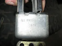
This started with the choke/manifold heater wiring. The 4cyl for some reason has a separate choke relay. Little metal box that was bolted to the PS fender.

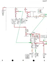
Now the relay is fed directly from the alternator. On a AMC 258 i6 / 4.2l this wire is spliced into coil/ignition module feed.
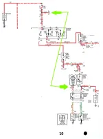
On the 4 cyl there is a resistance wire, from the same alt connector that the above wire is. It is spliced into the coil/ignition module feed.
Since the AMC 150 is basically a AMC 258 i6 / 4.2l with 2 cyl cut off, and the ignition module and coil are the same for both, why does one need a resistance wire and the other not?
On both, they are part of the ignition feed 10ga wire coming from the fuse block.
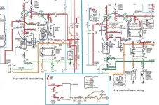
Ok, pretty much understand that I need to dump the resistance wire and do a little splicing to get to match the 6 drawings. But why is the resistance wire there in the first place? Why two different resistance rated wires feeding the same thing?
Does the 6 cyl alt connector have 2 wires coming from it, or just one? (don't have a 6 to look at, so a pic from one would be nice)
Have I just not found the resistance wire on the 6 cyl drawings?

BTW, I took the 84-86 FSM schematics and colored them in, along with an 83 version (easier to get an overall picture than the 84-86 drawings).
They are on Dropbox. When you open the file ther is a box in the top right hand corner with 3 "dots". Click on this and a menu comes down that will allow you to down load the file. There is a .jpeg file and a .png file (MS Paint) in case you want to make changes in paint.
84-86
https://www.dropbox.com/sh/gyg0lqi7gjkc5ja/AAALL3yDKB1X0AlsVMn_rcQ8a?dl=0
83 overall
https://www.dropbox.com/sh/4nbko8o5nqiwak0/AAA9ctAXSBIuNp06vDGK1SAFa?dl=0
Fuse box Cavity Chart
https://www.dropbox.com/sh/b5od1zm28w4ttvv/AAC8hnM6wA4__SQiA42GA_0Ia?dl=0
This started with the choke/manifold heater wiring. The 4cyl for some reason has a separate choke relay. Little metal box that was bolted to the PS fender.

Now the relay is fed directly from the alternator. On a AMC 258 i6 / 4.2l this wire is spliced into coil/ignition module feed.
On the 4 cyl there is a resistance wire, from the same alt connector that the above wire is. It is spliced into the coil/ignition module feed.
Since the AMC 150 is basically a AMC 258 i6 / 4.2l with 2 cyl cut off, and the ignition module and coil are the same for both, why does one need a resistance wire and the other not?
On both, they are part of the ignition feed 10ga wire coming from the fuse block.
Ok, pretty much understand that I need to dump the resistance wire and do a little splicing to get to match the 6 drawings. But why is the resistance wire there in the first place? Why two different resistance rated wires feeding the same thing?
Does the 6 cyl alt connector have 2 wires coming from it, or just one? (don't have a 6 to look at, so a pic from one would be nice)
Have I just not found the resistance wire on the 6 cyl drawings?

BTW, I took the 84-86 FSM schematics and colored them in, along with an 83 version (easier to get an overall picture than the 84-86 drawings).
They are on Dropbox. When you open the file ther is a box in the top right hand corner with 3 "dots". Click on this and a menu comes down that will allow you to down load the file. There is a .jpeg file and a .png file (MS Paint) in case you want to make changes in paint.
84-86
https://www.dropbox.com/sh/gyg0lqi7gjkc5ja/AAALL3yDKB1X0AlsVMn_rcQ8a?dl=0
83 overall
https://www.dropbox.com/sh/4nbko8o5nqiwak0/AAA9ctAXSBIuNp06vDGK1SAFa?dl=0
Fuse box Cavity Chart
https://www.dropbox.com/sh/b5od1zm28w4ttvv/AAC8hnM6wA4__SQiA42GA_0Ia?dl=0


