• Hello Guest, we are proud to now have our Wiki online that is completely compiled and written by our members. Feel free to browse our Jeep-CJ Wiki or click on any orange keyword when looking at posts in the forum.

1975 CJ5 Charging System

1975 CJ5 Charging System

Hedgehog

Always Off-Roading Jeeper
Posts
9,370
Thanks
4
Location
Tucson/Marana Arizona
Vehicle(s)
-1975 Jeep CJ5, 360 V8, Headers, Duel Exhaust,T15 transmission, D-20 Transfer case, Twin Stick Conversion, Warn 8274 Winch
-1951 Willys Wagon, 4 cylinder, "F" head, little rust, very close to stock
I have had this Jeep as a project for a few months now and I'm getting closer to actually driving it, but I have no real idea about the Jeeps ( the Witch) history.

When I got the Witch home and was doing a more or less complete inspection it was noticed that the alternator had an internal regulator, this is good. It seems to be a simple affair with a red wire (power) going to the hot side of the solenoid coming out the bottom back and two wires coming out of a plug in the side. The plug wires are black and white. The black wire is wired into the wiring harness, the white wire doesn’t seem to have a home and is sticking out kind of lonely like. After talking to Jeep guru Rob he said the wire is supposed to go to the ignition switch so I wired her up.

This weekend I fired the Witch up for the first time in a very long time. I noticed that the switch seemed to be hotter than necessary and the alternator was much hotter than it should be. Now I’m concerned and considering replacement. Any ideas or help with a proper, simple to wire replacement would be appreciated.

thanks
Michael
 
I would suggest finding out what kind of alternator it is, from your description, maybe a Delco SI series, pull up some internet pics and compare. Then you should be able to do a search and find out how to wire it.
 
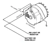
The wires are for an idiot light. T2 to 12v and T1 to the light.

attachment.php


gmalt.webp
 
So, If I read that correctly, the white wire really doesn't do anything? It just works when there's a problem?
 
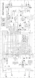
The white wire is the jumper in CJ's diagram. It important feeds into the regulator.
 
http://www.offroaders.com/tech/images/CJ-Wiring-Diagram-1974-1975.jpg

Sounds like your connector might not be stock based on the colors.

The warning wire should go to the "Splice B" power junction under the dash. It needs a lamp or low ohm resistor in series (10R shown in the schematic) to function properly.

The sense wire T2 needs to go through the splice in the engine loom, through the panel, then to "Splice A" under the dash. Splice A is the main power junction, feeding the headlights, various circuits through the fuse panel, etc. If you simply jump it to the large cable going to the relay, the alt. can't really sense the actual demand on the electrical system. Will probably still "work" but definitely not optimal.
 
Last edited:
The link takes me to a page full of topics. Which one should I hit to get me to the diagram you are using.
 
This is always odd, your link produced the very same result. If you can let me know which topic I need to hit we are in business.
 
I just updated my 73CJ to a powermaster alternator with the type you are describing. My upgrade was to a 10si type alternator and it appears you may have the same.

The internal regulator does not need the extra 2 wire connections to work properly. The "1" terminal is for the charging light in the dash. The "2" terminal is for a remote voltage sense which controls the voltage regulation point for the alternator output.

However, I have found that the newer 10si internally regulated alternators DO NOT use this wire at all. There was a time when this wire was simply connected back to the alternator output about 1 - 2 feet in the wiring harness as depicted on one of the diagrams on this post. I found that mine makes no difference at all as the regulator is internally connected. I confirmed this with a call to powermaster alternator.

If you are getting hot wires with this connected, I would remove it until you resolve what is occurring. If the alternator is charging at 13.8 to 14.5 volts properly, then I would say the extra wire is not needed.

If the regulator is using that wire to control the voltage, it is possible that when you connected it to the ignition switch, that the alternator raised its output very high to try and make the voltage sense connection be around 14.4 volts. If you have the original small wiring harness or poorly connected wires, which could create a voltage drop, then the alternator could potentially put out 16+ volts to make up the difference. Hard on the battery and everything else.

I would suggest you get a voltmeter and check the voltage at various points in the system to make sure all is ok. Check the altertnator output at the battery, alternator, ignition switch, etc.. to see what the system is doing.

Good Luck
 
Thanks, I did disconnect the wire to the ignition switch, it doesn't make sence to risk trouoble there. I've got to get out my voltmeter and start polking around looking for trouble.
 

Jeep-CJ Donation Drive

Help support Jeep-CJ.com by making a contribution.

Help support Jeep-CJ.com by making a contribution.
Goal
$200.00
Earned
$35.00
This donation drive ends in
0 hours, 0 minutes, 0 seconds
  17.5%
Back
Top Bottom