• Hello Guest, we are proud to now have our Wiki online that is completely compiled and written by our members. Feel free to browse our Jeep-CJ Wiki or click on any orange keyword when looking at posts in the forum.

Re-Wire starting... I Want to Test as I Go

Re-Wire starting... I Want to Test as I Go
i am installing the painless #10106 in my 76....

my question is this...

in the 10106 harness, there are 2 wires labeled 'to battery B+'... different ga wires... one is orange, the other, heavier red w/black tracer... where do these go?


the painless wires are as follows:

727 'front parking lights' - brown

730 'inst panel' - brown

728 'head light switch power B+' - red w/black tracer

729 'rear tail' - brown

759 'head light switch power B+' - orange

707 'dimmer switch' - blue w/yellow tracer

.. its gotten me to the point that i am afraid to hook any of them up, for fear of damaging something...

any and all help appreciated!

thanks!!

they cant connect to each other (i dont think), and theres only one post on the switch that is labeled 'to battery'

its gotten me to the point that i am afraid to hook any of them up, for fear of damaging something...

any and all help appreciated!

thanks!!
 
Last edited:
i am installing the painless #10106 in my 76....

my question is this...

in the 10106 harness, there are 2 wires labeled 'to battery B+'... different ga wires... one is orange, the other, heavier red w/black tracer... where do these go?


the painless wires are as follows:

727 'front parking lights' - brown

730 'inst panel' - brown

728 'head light switch power B+' - red w/black tracer

729 'rear tail' - brown

759 'head light switch power B+' - orange

707 'dimmer switch' - blue w/yellow tracer

.. its gotten me to the point that i am afraid to hook any of them up, for fear of damaging something...

any and all help appreciated!

thanks!!

they cant connect to each other (i dont think), and theres only one post on the switch that is labeled 'to battery'

its gotten me to the point that i am afraid to hook any of them up, for fear of damaging something...

any and all help appreciated!

thanks!!

This is why I don't like the harness makers...

RED, no tracer, should be full time battery power.
RED, w/tracer should be SWITCHED battery power.

BLACK should ALWAYS be a direct 'Ground' or Negative',
while 'Green' should ALWAYS be a 'Switched' 'Ground' or Negative circuit.

This mix and match :dung: is for the birds...

--------------------

DO YOU HAVE THE WIRING DIAGRAM FOR THE KIT YOU USED?

Get on the web site and see if they have a wiring diagram/schematic for the harness.
If you can't find one, you are going to do a LOT of tracing wires to see where they come from, and where they go in that harness before you can be SURE.
 
*TYPICALLY*...
The HEAD LIGHTS ARE SACRED.
The head light power comes directly from the 'Battery' (or battery cable at the solenoid, or from the incoming line to the fuse block, a direct 'Battery' feed),

Then through a CIRCUIT BREAKER built into the head light switch,
Then through the switch itself,
Then out to the dimmer switch,
Then out to the high/low beams.

Just because the park/tail lights work on the same switch DOES NOT MEAN the head light feed powers them!
The actual headlights are on their own circuit, with a self resetting circuit breaker built into the switch that handles ONLY the headlights.

The idea is,
If something goes wrong with the wiring TO the headlights, the circuit breaker kicks out, keeping the wiring from burning,
Then the circuit breaker kicks back in to give you head lights again.

When the headlight go out... ALWAYS KICK THE DIMMER SWITCH.
So when the circuit breaker comes back 'IN' you don't just kick the breaker again...

----------------------

SO...
HEAD LIGHTS ARE SACRED.
They *Can* wire to the feed for the fuse block,
But there won't be a 'Fuse' for 'Headlights'

The feed will go DIRECTLY to the headlight switch,
The headlight switch will have a circuit breaker installed in it,
The switch will have an OUTPUT to the head lights (Generic, same feed for high and low beams),

The DIMMER SWITCH will direct the OUTPUT from the switch to high or low beams.

------------------

Now,
The 'High Beam Indicator' in your dash will have a smaller wire connected to it.
That smaller wire will need to be crimped into the 'High Beam OUT' line DIMMER SWITCH,
To the high beams for that indicator light to work.

When the HIGH BEAMS get power, so should that 'High Beam Indicator' wire/light.

The LOW BEAMS come directly from dimmer switch to low beam headlights.
No one uses a 'Low Beam INDICATOR', so there isn't an extra wire in that connection.

----------------

Again,
POWER SUPPLY (Battery)>----->Breaker/Head Light Switch>----->Bright Dim Switch

From Bright/Dim Switch there will be TWO outputs,
1. High Beams/Indicator
2. Low Beams

Does this help explain things?
 
Instrument Panel wiring should come from HEAD LIGHT SWITCH, but from the Variable Resistor built into the switch.

The rotation of the head light switch knob should make the panel lights Bright/Dim on a sliding scale.

Lots of complaints that the dash lights 'Don't Work' when the dimmer knob is cranked all the way down...
So remember to turn that knob before you declare the circuit NOT WORKING.

That same circuit is sometimes connected to the interior lights,
So make sure your dash works FIRST,
Then think about connecting to the interior lights later.

The reason is, the interior lights have SWITCHES, and some of those switches or wiring will screw with your testing...

------------

The second type of headlight switch will have a separate circuit for your interior lights.
The 'On/Off' switch is built into the dash light dimmer,
Crank the knob COMPLETELY one direction or the other, and the interior lights will come on, but won't dim with dash lights.

I don't know which headlight switch you have, so I'm telling you both ways...
 
Rear tail lights, (Brown)...
Jeeze, they must have got a deal on 'brown' wire...

Anyway, that's an output from the headlight switch, through the fuse block to 'Tail Lights' and on to the back of the vehicle to the tail lamps in the back.

Some people wire the rear side markers and plate light to the 'Tail Lights', and that is acceptable.
------------

The 'Park Lights' in the front are another story...
This is a COMPLICATED wiring mess on a CJ for the front 'Park' lamps since the side marker/fender mounted lights have to show your front turn signals work...

WHEN WIRED CORRECTLY,
The side marker lamps will flash ON/OFF with the turn signals,
And will stay 'ON' with the park lights.

The front grill lamps have TWO FILAMENTS, a 'High' and a 'Low'.
Low is the park lights,
High is the turn signals.

Since side marker lights only have ONE filament, they have to flash ON/OFF to be legal in most states.

There is a 'Trick' to the wiring in the front,
The side marker lights DO NOT 'GROUND' directly,
They get 'Ground' through the turn signal filament in the grill bulbs.

This *MIGHT* explain the way these things need to be wired, and you will have to do the wiring since you only get ONE park lamp feed,
This DOES NOT come with the 'Painful' harness...

FrontSideMarker01.gif


In the 'Electrical Basics 101' thread I spend a LOT of time on these screwy park/turn wiring diagrams because they are the most confusing to an electrical 'Noobie'...

There is also a way to get rid of a ton of those 'Spices' shown, and that is also in 'Electrical Basics 101',
You use CONNECTORS and a little extra wire to get rid of the SPLICES everywhere.
Basic electrical connectors, nothing fancy, you can get them anywhere.

SpliceHappy02.gif


SINCE your park lights come with 'Plugs' often times,
And if they don't have plugs, it's easy to install plugs...

SpliceCrimp01.gif


By backing the terminals out of the connectors,
You simply crimp in an extra wire for the side marker lights, and put the terminal back into the connector.
This allows you to 'Plug & Play' the side markers with the turn signals in the front without a bunch of splices everywhere at random places in the harness.

Makes tracking down bad connections MUCH more simple!

.

.
 
Last edited:
The 'Orange' power wire *SHOULD* be, and I'd test it,
Should be the power feed TO the headlight switch that powers up the 'Accessory' lights.
Stuff like tail lights, marker lights, dash lights, ect.

That headlight switch is a complicated beast.
There is a DIRECT current path for the head lights,
There is a SECONDARY current path (Orange wire if I'm understanding this correctly) that powers up all the other lights.

The interior, dash, tail, park, ect. will have a SECOND FEED for them, separated from the headlights only power feed.
If I'm correct, then with the ORANGE WIRE DISCONNECTED, the dash, tail, park lights SHOULD NOT WORK.

With the 'RED' wire disconnected, the head lights Only should not work.

The wire marked 'Dimmer Switch' is the head light ONLY power from headlight switch TO THE DIMMER SWITCH, then you will have to make the wires from dimmer out to headlights.
(See why I call it 'Painful'? So much is missing and they don't tell you about it)

So, you will have High & Low beam wires to the grill,
You will have Right & Left turn wires to the grill,
You will have 'Park' lights to the grill.

Then you will have to make the harness that makes those feeds work,
Along with a good, solid 'Ground Path' wire to make all them work CORRECTLY once you get power up there to all the bulbs...

This isn't NEARLY as complicated as it sounds.

The 'Park' wire hits the front grill lamps, small (dim) filament side, and it hits the side marker lights,
All on one feed up front. You just make your harness start at the Passenger side marker light,
Move over to the right front grill lamp, then the left front grill lamp, then the left side marker light.

The other side of the side marker light on the left connects to the left turn signal filament in the left grill lamp where the left turn signal wire goes.

The other side of the RIGHT marker light does the same for the right turn bulb/connection.

High beam goes from left high beam connection to right high beam connection.

The low beam connection goes from left bulb to right bulb low beam connection.

Start your 'Ground' at the LEFT front grill light SOCKET HOUSING, since there isn't a dedicated 'Ground' wire to the socket, you connect to the metal shell,
Go up to the head light on the left, then to the headlight on the right (middle terminal) and down to the front grill shell on the RIGHT, then out to a dedicated 'Ground Path' to the battery.

Like I said, this isn't as complicated as you might think,
Would a diagram help? The wiring diagram (minus dedicated 'Grounds' is in the service manual, if you need help understanding it, I'll help.
 
TR

let me get my fecal matter together and make some notes and have yet another look at the diagram...

i'll tell you what i have done, what works, what doesnt and anything else i can think of... it'll take a bit to get it all together (couple hours) and a diagram WOULD help, but i DO have one on the wall in the garage so i can look as i go... i'll post pix too so maybe it will help you follow along with my 1/2 arse explanations...

i also have the pdf instructions for this particular kit if you want to see the manual

thanks for the info to date... some of it seems to make sense, some doesnt... according to the painless instructions anyway...

NO there was NOT a diagram IN the kit... i am assuming that most people swap in/out as they go when replacing the harness...

FWIW, this is the switch i am using... the one on the RIGHT is my exact switch

HeadLightSwitchJumperNotes.JPG


i'll be back

thanks again!
 
Last edited:
OK TR... here we go... i'll see if i can write this up in a way that makes sense...

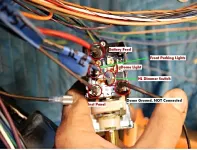
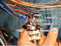
heres the switch in place

b84e3d93-0f0f-467f-977e-ef7953e000b5_zps8585f415.webp

which is how i got it from the schematic that i have... which i cant find on this computer, but i think its from the TSM...

looking at said schematic, this is what i see...

Starting at splice 'A' (location C7 on the schematic):

12A RED goes to the dash panel, where it becomes 12C RED and runs to splice 'F'... where it becomes 12D RED, runs to a fusible link, and becomes 12A RED (again)... it then runs to splice 'E' where it becomes 12B RED and attaches to the 1/4" stud on the alternator

12B RED runs to the dash panel, it becomes 45 RED w/tracer and goes to the horn

12C RED runs to the hazard fuse on the fuse block

12D RED runs to the battery feed on the headlamp switch

12E RED rund to the ignition switch

12F RED runs to the cigarette lighter...

what i did last nite was:

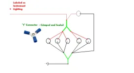
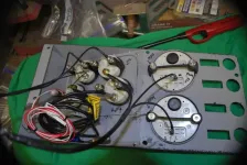
apply 12V to the battery feed on the light switch, and run 730 brown from 'dash lights' post on lamp switch to the gauge lighting circuit i built (see below)

Gauges2_zps35307704.webp

DSC_5282_zps260056f9.webp

the gauge lights csame ON, but would NOT vary in brightness while turning the knob... they DID however go out when turned all the way to detent

i also attached 730 to the 'dome' post on the switch to see if it would vary with the knob... no luck, and 'dome ground' was NOT connected to anything

per the painless instructions, i now have 235 'volt meter source dash power B+' (red w/white tracer) wired in parallel to ALL of the gauge 'I' terminals...

i have NOT applied power to this set up, nor have i connected the 'S' terminals on the gauges to anything...

i havent applied power because it doesnt make sense to me why the volt meter source would connect to all of the 'I' terminals, when the instructions for the volt meter (AutoMeter) say to hook it to the ignition switch... UNLESS, the volt meter AND the rest of gauges get all of their power from there... but that is a series ckt and im not sure i like that idea...

the JEEP and i are NOT on speaking terms today, and i am hoping that she can see the error of her ways...

i hope this makes some sense to you TR...

thanks for your help... there WILL be more questions

TB
 
Dash Lamps,
Do this little test...
Take a lamp, any lamp, with a fuse inline.
I'm sure you have a fuse someplace,

Connect from dash lamp feed, 'Ground' to the interior light 'Ground' terminal and see if they dim when the knob is rotated.

Some dash lamps have TWO WIRES, those are 'Controlled Ground' sockets,
While others have only one 'Hot' wire, those 'Ground' through the lamp holders.
They usually have METAL 'Fingers' that hold them in the holes.

Since you changed ALL your gauges, they should have controlled 'Ground' sockets, and you can just do a parallel 'Ground' to go back to the headlight switch.

The older CJs you COULD NOT dim the dash lamps,
The newer ones, because of the switch used, you COULD control the dash lamps if AMC had used controlled ground sockets, but they didn't.
That's just one of the things I add when I do a harness for a CJ is dimable dash lamps.

------------------------------

When I see this, it sets my teeth on edge.
Where is the head light switch plastic connector off the old harness?

b84e3d93-0f0f-467f-977e-ef7953e000b5_zps8585f415.webp

With a few Packard terminals you can punch out the old wiring, stick your new wiring right in that connector and have it 'Plug & Play'.

If this is the way you are testing before you re-terminate with Packard and connector, you are fine...
I understand your hesitation with the questions.

---------------

Since I don't know what fuses you got with Painful,
I can't make a call on this, you will just have to check and see.

Dash/Dome-Interior/Brake/Turn/Park lights USUALLY have FUSES.
See which wires come FROM the fuse block, and see if there are fuses for those circuits...

*IF*...
You see a fuse for say PARK LAMPS, then look for another wires marked 'Park Lamps' in the outbound bundle.

Battery>----->Headlight Switch>---->Fuse>----->Tail Lights.

The power would come from your switch (Battery +), though the fuse, then out to the lamps.

-------------------------------------------

*IF*...
There is no fuse marked for what you are hooking up, then it's power from the switch directly to the lamp you are hooking up.

This further confuses things...

------------------------------------------

OK, you made me go look at the PDF from Painful...

HEADLIGHT SECTION B.

Red w/Black Trace, 12 Ga. #728 *7,
*7, This wire is power for the portion of the headlight switch that goes out to the headlights and front parking lights.

In your case, it powers EVERYTHING in the head light switch, dash, park, head, tail, interior.
And they only used a 12 Ga. wire... Makes me wonder about 'Painful' and the one size fits nothing harnesses.


Blue/Yellow Trace, 14 Ga, #707, From headlight switch to dimmer switch.
This is the master headlight power feed TO the headlights.

Brown, 14 Ga. #729, From headlight switch to tail lights.

Brown, 18 Ga., #727, From headlight switch to park lights.

Brown, 18 Ga. #730, *6.
*6, This is a short length of wire that is not connected on either end, (Just loose in the box I suppose)
Headlight switch to instrument panel lights.

Orange, 14 Ga. #759, *8,
*8 This wire is power for the portion of the headlight switch that goes out to the instrument panel lights and the taillights.
This wire will not be used if your headlight switch has only
one power terminal.

If you had a newer headlight switch, you could use this.

-------------------------
 
Dash Lamps,
Do this little test...
Take a lamp, any lamp, with a fuse inline.
I'm sure you have a fuse someplace,

Connect from dash lamp feed, 'Ground' to the interior light 'Ground' terminal and see if they dim when the knob is rotated.

i'll make an inline fuse tester and try this test on one of the small dash lamps instead of the gauges (theyre cheaper)
Some dash lamps have TWO WIRES, those are 'Controlled Ground' sockets,
While others have only one 'Hot' wire, those 'Ground' through the lamp holders.
They usually have METAL 'Fingers' that hold them in the holes.

ALL of my dash lamps have also been replaced, they all have plastic housings and 2 tabs on the back, and function with power/ground applied so this test will be easy enough

When I see this, it sets my teeth on edge.
Where is the head light switch plastic connector off the old harness?

there is no plastic cover, the original harness was pulled a LONG time ago... and is long since trashed... all i have left is the OE column and whatever was attached to it... OE dash light sockets, courtesy lights and thats it... was pulled before i knew what i was doing

this being the case, replacing packards in an original plug is not possible...

HEADLIGHT SECTION B.

Red w/Black Trace, 12 Ga. #728 *7,
*7, This wire is power for the portion of the headlight switch that goes out to the headlights and front parking lights.

In your case, it powers EVERYTHING in the head light switch, dash, park, head, tail, interior.
And they only used a 12 Ga. wire... Makes me wonder about 'Painful' and the one size fits nothing harnesses.

i have this (red w/black tracer) wire connected to the switch as of this writing, based on the PDF notes...

Blue/Yellow Trace, 14 Ga, #707, From headlight switch to dimmer switch.
This is the master headlight power feed TO the headlights.
connected correctly, on the headlamp switch...

Brown, 14 Ga. #729, From headlight switch to tail lights.
which terminal is for the tail lights on my switch? the pic i used originally (not the one of mine) doesnt specify...

Brown, 18 Ga., #727, From headlight switch to park lights.

connected correctly, on the headlamp switch...

Brown, 18 Ga. #730, *6.
*6, This is a short length of wire that is not connected on either end, (Just loose in the box I suppose)
Headlight switch to instrument panel lights.
wasnt loose in the box, just wasnt attached to anything and had no terminals/connectors... i installed a terminal, and attached it to the 'inst panel' post on the switch to provide power to the dash lights... which lights the gauges when 12V is applied to the 'battery power' post on the headlamp switch, and negative return is provided

Orange, 14 Ga. #759, *8,
*8 This wire is power for the portion of the headlight switch that goes out to the instrument panel lights and the taillights.
This wire will not be used if your headlight switch has only
one power terminal.

If you had a newer headlight switch, you could use this.


would a newer switch (year range please) make this easier? and if i have to use the current switch i have, does this wire remain un-connected on both ends?

i'll try these tests after i get home from work and run some errands... this being a holiday week, JEEP will have a little less attention until after the holiday...

thanks TR... check your PM box, please
 
Last edited:
Most of this is going TO something, so you just hang a light bulb on the wire and test it.
If there is power to the fuse block, or the 'Bat' terminal on the switch, it should work.
 
spent the evening organizing my electrical stuff... to make it easier t work in the garage...

did apply power to the switch... pull out knob to parking lite ON position, gauge lights came on, no variance with knob rotation... the more I think about it, the more I think you may be right that I have no dash dimming capability with this switch (no switched ground as you stated earlier)...

I do NOT have my dash lights (small white lights for fan/lights/wipers) hooked up yet as I think I may try to hook them in parallel...

built a sealed dedicated negative return box to install aft for anything behind the seats... will run a 10ga minimum to the neg battery post for good solid returns...

heres a question that came to me though... if I don't have a battery installed, and my only neg return is the one that's provided by the power converter, the only things that will work are the things that are connected to whatever I get power to and that also have a neg return...

I know this seems obvious, but for some reason, I am stumped...

its going to be easier if I can break each of these circuits into smaller, more manageable pieces.. parking lights... then headlights, then dash or something similar...

I DID check for continuity at the dimmer post on the lamp switch thru the dimmer switch, but I think that since I don't have the front 1/2 of the harness connected, theres nothing to read anywhere at the other end...

I think im going to have to hook up the front 1/2 of the harness and let it hang loose and pick out what im trying to check, as well as make a simple ckt with a bulb in it to check for voltage at different points coming OUT of the lamp switch...

basically, im thinking out loud, and probably making this WAY harder than it actually is

im also wondering about my multimeter...its a Sperry that I've had for 100 years... it has a new battery (9V) but I don't know how accurate it is... are there ways I can check it?.. and if its goofy, whats a GOOD mid-range meter to look at?

I shop here

http://www.delcity.net/

so if someone could offer a suggestion, I would appreciate it...

pretty normal for me =/

as always... thanks a boat-load

mk
 
If you want to test the lights,
Supply the switch with FUSED positive,
And supply the light(s) with negative from the same power source, so the circuit can complete itself.

The fuse will depend on what test light you are using.
If its a small light use a 3 or 5 amp fuse,
If you are hooking to full headlights (both) use a 20 amp fuse.

You are over thinking this,
Just hook positive to supply, negative to 'Ground' and test your light harness,
And switch the same thing, power up the switch,
Give your test light a 'Ground' and pull the switch on, see if your test light does its thing.

i think youre right TR... overthinking it to death!

todays update...

went to the FLAPS and got a 30 amp max fuse holder, and a light socket to make a tester, and some small LED strips for courtesy lights... picked up some more wire too... in colors

came home and got to working on the headlamp switch again...

wired my dash knob lights (the white ones) on parallel... with separate dedicated negative return wires for the gauges and the dash lights... tested them, and they ALL work, gauges too!! :chug:... they come on with 12V on the 'battery' post on the switch, both grounded (common post)... with the headlamp switch pulled out to the 1st detent

YAY!!

next is the wire 'tail lights' im thinking that they are wired into the HL switch on the same post that is labeled 'parking lamps'... ill use the test light im making to check it...

i was looking at the front section of the harness, and i didnt see a set of wires labeled as 'to headlamps' so i'm also guessing that i may have to run that myself... which id fine, because im am leaning toward HiDs or similar and the OE 18ga wont carry that load (i dont think)

heres a fusing question... do i need to add a fuse above and beyond a ckt that has a fuse in the fuse panel already?

and, do i need to add a fuse to any and all new ckts that i run? (do i need to fuse all the feeds for the work i have done to date?

thanks again TR for all the insight and advice!
 
Like I wrote on the first page...
"WOW! Are you in for an unpleasant surprise!"

Some more bad news...
And the guys that installed the same harness, did NO testing will argue this, but here are the FACTS.

I don't believe in a 'Sliding Scale' to see what you can get away with,
Either it's 'Safe' or it's 'Fail-Safe' and there isn't a 'Gray' area in the way I do things...
Just because "99% Can Get Away With This Or That",
DOES NOT MEAN IT'S RIGHT, CORRECT, or 'SAFE ENOUGH'...

-----------------

Power IN,
The master power to the fuse block needs some sort of 'Fuse' to protect the WIRE from battery to fuse block.

In a stock harness, that's a FUSIBLE LINK at the starter relay connection.

With Painful, that's usually a 'Maxi Fuse'.

Now, fusible links were installed from the factory,
And unless you do something stupid, like ground out the 'BAT' terminal on the alternator or rub/pinch through the master power wire to the fuse block they worked 30 or 40 years without fail...
Since they were SEALED UP with the rest of the wiring harness.

The 'Maxi-Fuse' sockets are usually NOT sealed.
They are a magnet/catch basin for everything that flies around the engine bay, spray from tires, whatever runs down the wire into the socket, ect.
I find corrosion in EVERY maxi fuse socket I've had to deal with...

And the 'Fuse'/wire protection MUST go out there on the fender, as close to the starter relay as is practical to protect the WIRE going to the fuse block.
So no hiding it someplace less exposed...

-----------------------------

REMEMBER!
The 'FEED' to the head lights AND the fuse block is only 10 Ga.,
See the Brown & Sharp scale posted.

When the headlights alone can draw 30 Amps,
AND,
All the gauges, other lights, and everything else is drawing off that 10 Ga. feed through the fuse block which can only SAFELY support 32.5 Amps...
And,
You are considering HIGHER DRAW HEADLIGHTS...

----------------------------

NOW...
Painful *Usually* puts in fuses that are WAY TOO BIG for the wire they are *SUPPOSED TO PROTECT*...

That's why I often recommend you REWIRE your old fuse block yourself,
Just install new wires on the old fuse block,
Or swap in something with NEWER type fuses instead of going 'Painful' or some other pre-made fuse block.

Remember, Fuses protect the WIRE to the electrical device...
If that wire gets DEAD 'Shorted' to 'Ground', the wire is going to try to burn INSTANTLY...
And the fuse will usually protect the wire, but too late, the insulation will melt and the wire will be damaged beyond use...

But if that wire gets PINCHED, or rubbed through,
The 'Short' might NOT be total (Dead Grounded),
And the wire heats up SLOWLY, the fuse doesn't blow and you get a fire...

The WIRE should always be of larger current capacity than the fuse.
That's why I posted the Brown & Sharp wire gauge/capacity chart...

COLUMN 1, WIRE GAUGE SIZE, COLUMN 4 AMP LOAD CAPACITY

B&Sscale01.gif


Notice say, a 12 ga. wire will conduct 23 Amps without heating up.
Your head lights usually have a 25 to 30 Amp fuse on a 12 Ga. wire (or smaller) and this is simply NO GOOD!

If the 12 Ga. wire will conduct 23 amps, then you should use no larger than a 20 Amp fuse TO PROTECT THE WIRE.

If a 10 ga. wire will conduct 32.5 Amps, then you shouldn't use anything larger than a 30 Amp fuse TO PROTECT THE WIRE.

-------------

The 'Factory' did testing, they found that they could SLIGHTLY heat the wire during 100 duty cycle and get away with it,
And that became the new 'Standard'...
For a PARTICULAR INSULATION.

Since this isn't 'Factory' wire, we don't have any idea what insulation is on it, or what it's melt/burn point is...

Some things you shouldn't mess with...
Like burning your vehicle down in the garage at 3AM when everyone is asleep...

-------------------

DEAD SAFE/'FAIL SAFE'!
THE FUSE SHOULD BLOW BEFORE THE WIRE HEATS UP!


Check the OUTBOUND wire gauges from the fuse block, and use the appropriate fuse for that WIRE SIZE.
No matter what 'Painful' or any of the other makers recommend...

And remember this,
The battery produces CURRENT.
Current can come through as Voltage or Amperage.
As Voltage decreases, AMPERAGE INCREASES.
As the battery runs down and can't produce VOLTAGE,
The AMPERAGE will increase.

AMPERAGE is what burns vehicles down.
That's why 'Fuses' are rated in AMPS.

--------------------------

I'm using headlights here because the headlights are the largest draw outside of the starter motor or winch...

Now, there IS a solution to things like headlights that will draw 20 to 30 Amps at 100% duty cycle.

And that's STOCK headlights. If you use higher output lights, the amperage to make that extra light INCREASES DEMAND.

TESTING the amperage draw of your headlights is a good idea,
See if the wiring provided is up to the task.
All it takes is an amp gauge and a little time...
Simply HOT WIRE one or both of your headlights with a supply, a 'Ground Path' and an amp gauge in the supply line...

*IF* your chosen headlights DO NOT exceed the AMP CAPACITY of the wire used to supply them,
Then you are fine running the supply through the switch/provided wire.

If you EXCEED the amp load capacity of the wire gauge used, then it's time to do something about it...

If your headlights demand more amperage, voltage drops on the line to the head lights or the amp gauge shows more draw than the supply wire can SAFELY handle,
Then there is a solution...

That solution is head light relays.
A FUSED direct feed from battery supply to the headlights that is controlled by the head light switch.

LARGE, FUSED wires to the relays/headlights,
Small wires from switch activate the relays.
No fuss, no screw ups, FAIL SAFE built in.
And, it's pretty easy to do without buying one of those headlight wiring packages that *May* or *May Not* have 'Correct' wiring gauges/fusing when it gets to you...

----------

Taking the headlight draw OFF OF the master power to the fuse block is one of the single best things you can do for the feed to the rest of your lights, gauges, ect.

Headlights on relays do this extremely efficiently,
AND,
Headlight relays supply the headlights with the current they need to work at their peak efficiency.
It's a Win/Win for your headlights and UNDERSIZED/OVERWORKED wiring harness.
 
Last edited:
I was planning on going with a relay for the headlamps themselves, for just that reason... to keep the wiring in the cockpit safe, and to provide the lights with what is basically 'straight, full strength power'... so i am on the same page with you there...

would a Bosch style relay with 87a and 87b (SPST, i believe) circuit work in this case?

installed in this manner (power the coil of the relay with wiring from the headlight switch with smaller ga wire, and run the heavier ga wire thru the contacts of the relay to power the lights)

i printed out the chart you provided earlier and have checked the wiring size/fuse arrangement and it looks to be acceptable... however i plan to check it again just to be safe... and for my own peace of mind

heres another question...

i installed two (2) 4" LED strips to use as courtesy lights and planned to run them off of the 'dome light' post on the headlamp switch... so they would come on with the rotation to detent of the knob... but that post is not getting any power

HeadLightSwitchJumperNotes.JPG


keep in mind that the gauges come on full strength with the knob pulled out to 'parking light ON' position, 'headlamp position ON', and DO dim with rotation of the knob and that all of the gauges and knob lights are wired in parallel...

there IS continuity between the 'dash' and 'dome' light posts, that varies with the rotation of the knob (as it should for dimming of the gauges)... with the knob rotated to detent (for dome light ON) continuity is 'full'... rotate the other way and continuity drops to zero (gauge lights OFF)...

how do i get power to the courtesy lights thru the headlamp switch?

and does the 'dome light ground' post go to a standard negative return point?


FYI - i also tied the 'tail light wire to the front parking light wire at the headlight switch, installed a test light, and checked the operation of the tail lights... the test light comes on when the knob is pulled to detent for parking and headlight ON... so THAT works as advertised...

i AM finding it easier to break all of the ckts down into smaller bite sized pieces and completing them one at a time is much easier, and problems can be addressed as they arise... your input/direction is paying off!
 
Last edited:
i was mistaken... what it should read is that when the 'dome ground' is returned to negative at the headlight switch, the courtesy light stays on at all times, regardless of knob position...

it appears that i am missing a ckt leg somewhere...

i understand the concept that the dome light comes on when the doors open (the switch controls the ground or feed to complete the ckt for the light to come on) so it makes sense that it would be hot all the time...

im thinking that i am missing what would take the place of the door jamb switch... whats the solution for this?

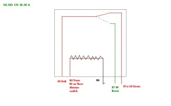
i also got some relays today for the OE headlamps and eventual upgrade... and think that wiring it this way will make it work... using the floor dimmer switch to energize the relay to power the high beams...

thoughts please...

HLHI-LORelay_zps73fe7965.webp

i am also going to have questions regarding the 'signal' wires from the harness to the gauges... 2 (temp and oil) are mechanical and require no signal from a sending unit... the tach should get its signal from the coil, the speedo is electric and will get its signal from the sending unit on the tranny... fuel is simple enough... and volt meter gets the signal from the alternator (i believe, i'll have to look at the docs to make sure before i hook it up all the way)...

so right now, what i am looking for is the answer to the courtesy light condition, and if my thought for the headlamp relay wiring is correct...

thanks!
 
OK, you just opened another can of worms here.

LED lights take very little power to operate, and that's good in most cases...
The deal here is, since they draw so little power, they are hard to control for brightness. There will be a very small threshold of resistance that dims them or puts them out completely.
It's going to be about 1/100 the resistance range of your dash lights.

LEDs never work on the same sliding scale as incandescent bulbs do,
And unless specifically designed to work with a common dimmer, they simply won't.

-----

Your other question, about the curtosy lights,
You need a switch.

Usually, if you rotate fully bright there will be a 'Click',
A detent that turns on the interior lights.
If your switch has that (I'm on the road and can't look right now),
Then you can hook up to that terminal and just rotate the knob for interior lights.
 
Last edited:
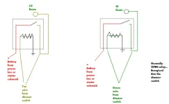
i have the interior light detent, and i also think i figured out how to wire a relay for both the lo-beam and hi-beam ckts for the lights... i think this will work as opposed to the single relay idea that i thought of in the previous post

HLHI-LORelay2_zps564d1592.webp


i am aware of the need for resistors to be used to drop the power to the LEDs (such as a 'wheat light style') but thought that maybe, since these appear to be plug and play, it would be easier to do just that... plug and play

Alpena Flex LED 8", White 77443: Order best L.E.D.'s & Strobe at Advance Auto Parts

the instrx provided read black to negative return, and black with tracer to 12V fused power source... simple enough... and it may be that since there is no battery in the jeep at this point that making the connection to the negative on the headlight switch WILL work, but since the tub isn't grounded, and i have to ground all of my testing ckts to the converter i am using, that it wont work as its supposed to until the tub is grounded to the battery...

since my gauges do not have turn signal indicators, or a hi beam indicator, and i also dont have a parking brake indicator light or a 4WD light, i want to use small lights such as these...

LED Indicator Lights - Pre-Wired

i'll do the required E = I*R to find out what resistance value i need and solder them into the ckt as well as replace the flashers with LED flashers for turnsignals and hazard lights...

will this relay set up work for the headlamps, and if wired with the correct gauge, push the H4 style lights if i choose to make that upgrade later?
 
Last edited:
Headlights are SACRED!
You don't want ANYTHING to interrupt you primary (low beam) headlights.

I usually recommend the Low Beams, since they draw less current,
Come directly from the switch to headlights.
This galls some people for some reason, but let me explain...

*IF*... Your low beams DRAW do Not exceed the wire gauge size supplying them, you wire them direct to the output of the switch.
This way they are on all the time when the switch is on.

They stay on when the high beams are on (Relay) adding more light when the high beams are on.
With halogen lights, the added heat will make the bulbs last longer,
The high beams are on a relay, so the switch gets some relief,
The low beams bypass the dimmer switch, so of the dimmer fails you still have low beams.

Even on a relay, if the head light switch fails the high beams are not going to work since there isn't any power from the switch to power the relay or low beams.

If you use a relay on low beams, that's adding a failure point, so use the very best relay you can find, and use waterproof relays.
GM used waterproof relays from the factory, so they aren't hard to find in the salvage yards or the parts stores or GM dealerships.

When I get home in a couple of days I can send you pictures, diagrams.
 

Jeep-CJ Donation Drive

Help support Jeep-CJ.com by making a contribution.

Help support Jeep-CJ.com by making a contribution.
Goal
$200.00
Earned
$0.00
This donation drive ends in
0 hours, 0 minutes, 0 seconds
  0.0%
Back
Top Bottom