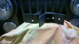
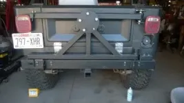
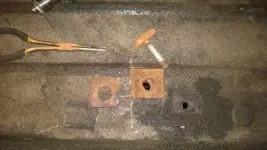
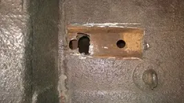
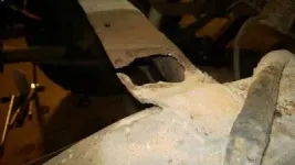
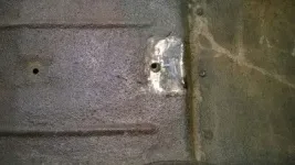
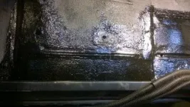
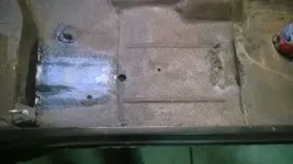
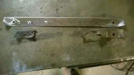
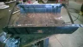
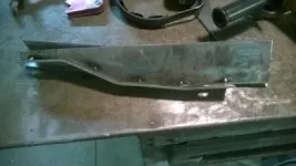
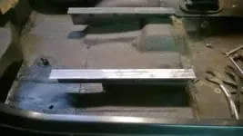
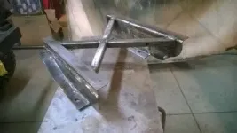
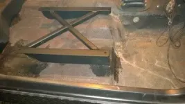
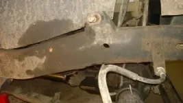
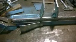
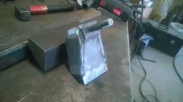
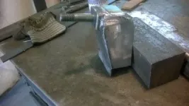
If you find it does pull at the sheet metal put some steel plate on the inside of the tub where the carrier mounts to strengthen it and disperse the tension.
Pete, there are steel plates inside of the body, I did think that far ahead

. Also forgot to mention, rubber insulators at each of the lock down points.
I think your bearing issue is why folks including myself use tapered wheel bearings for this type of hinge. If tight there is no bearing sloppiness there. At that point the spare tire movement is from metal flex not a loose bearing.
I put a lot of steel in my tire carrier with only one truly solid attaching point, the tapered bearing, and one latching point. When closed the latching point carries some weight, but the bearing carries the major part of the load. I actually do fear that it won't hold all the weight. Itself + 5 gallons of water + 5 gallons of fuel + the tire hanging off the rear. We will see how long mine lasts. I'd like to do just as you have done by using a second mounting point.
Hedge, my concern exactly. I haven't figured it out yet, but the plan is to also mount a gas can and the high lift jack on there at some point. I just tend to over build things because I worry about things coming loose, though I do like Lumpy's suggestion of attaching a return address label just in case!


Almost forgot about the 'non-flex'n frames' thd.

At least put a return address on the carrier-

:shooter:
Can you post a couple pictures of the carrier in question?
Would like to maybe steal some of your ideas.
BTW-With all that steel behind you. I now know why you like that V-8 so much

LG
At the risk of rekindling the "flex/non-flex" debate.


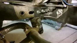
A bit more info. (I will try to add some pictures later) on how the bumper is attached. As I said, the bumper itself is made of 2"x4"x1/4" tube. What I didn't post yet is how it is attached to the frame. Behind the 2x4 bumper itself, is an additional 1/2"x4"x12" plate on each side sandwiched between the bumper and the rear cross member. Behind each cross member is a 3"x3"x3/16" gusseted angle which further ties the bumper to the cross member, to the frame. All this is held together with 8, grade 5, 1/2" bolts through the bumper, frame, and angle, and 4, grade 5, 7/16" bolts attaching the support angles to the frame. I am using the same engineering principals as are used when joining 2 "H" or "I" beams in a building, in that it is the friction between the steel plates that is created, based on bolt torque that creates the structural strength, not the sheer placed upon the bolts.
Though I will abstain from the "flex/non-flex" debate, it would be pretty much impossible for a light weight vehicle like a CJ, to manage to cause enough flex to what I have just described, to cause body deformation, or sheet metal tear out. At least, right at the rear where the carrier is mounted...........................
I do have to admit though, after all the problems that I have had today, you guys did have me thinking................$%^&@$#%@%$#$%


......................at least for awhile.


 Almost forgot about the 'non-flex'n frames' thd.
 :shooter:


