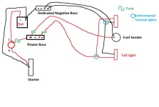
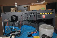
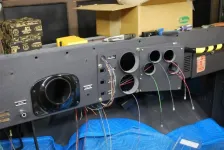
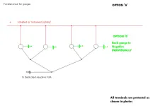
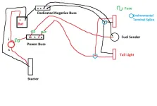
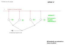
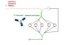
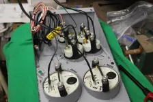
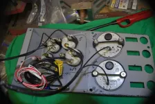
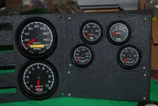
OK, lets take a simple circuit from the CJ...
the fuel sending unit... i have an aftermarket gauge (if that matters)...
if i am reading this correctly (about dedicated connections) then what *I* understand this to mean is as follows:
instead of grounding the sending unit on the frame in the aft section of the vehicle, a NEW DEDICATED wire should be spliced onto the ground wire (environmentally protected) and run all the way forward to the ground bus bar to provide a solid, reliable ground connection?
doesn't this extra length of wire effect (affect?) the circuit in some way... like the loss of voltage in a VERY long extension cord?
1. You don't have to run an EXCLUSIVE wire to the sending unit.
A GENERAL DIRECT 'GROUND PATH' for the rear lights, sending unit, ect. is fine, Just get to the back with a DIRECT GROUND PATH (one wire) then splice off for each tail light, sending unit, ect.
2. Do you think that DEDICATED COPPER ELECTRICAL CONDUCTOR in the 'Ground Path' I recommend has as much resistance as the steel tank, steel frame, Rusted/Corroded/Painted surfaces it has to connect to ever few feet,
And then struggle from frame to engine (*IF* there is still a working 'Ground' strap from frame to engine, a BIG *IF*...)
The struggle through the engine block, through rusted head bolts/bolt sealer, head gasket to the engine head,
THEN through more cast iron to a questionable 'Ground' connection at the engine head (another rusted/corroded/painted surafce connection),
Then FINALLY reach the 'Ground' cable bolted to the head that goes to the battery NEGATIVE?
Do you REALLY think that is more ELECTRICALLY EFFICIENT than a protected, actual ELECTRICAL CONDUCTOR with a DIRECT GROUND PATH to the battery negative?
---------
One other thing you might consider,
Most AFTERMARKET fuel sending units for custom gauges will NOT warranty the sender or gauge if there isn't a dedicated 'Ground' wire.
These are SENSITIVE ELECTRICAL DEVICES, the CLEANER the electrical pathways and connections, the more accurately they are going to work,
And the better you seal up that DIRECT ELECTRICAL CONNECTION, the LONGER they are going to work CORRECTLY...
The 'DUMBEST' of all electrical is a light bulb.
It's a direct 'SHORT', and most of these guys can't keep LIGHT BULBS WORKING!
(and then they argue about the 'Frame' being a good 'Ground'...)
The truth is,
THERE IS NO SUCH THING AS A 'GROUND' IN DC (Direct Current) wiring.
The term 'Ground' is referring to AC (Alternating Current), and it's shortened from 'Earth Ground'.
DC wiring has POSITIVE & NEGATIVE, there is no 'Ground' in that unless you plan to drag a long cord wired to an 'Earth Ground Rod'...
And that sill won't work since DC doesn't work with an 'Earth Ground'!
'GROUND' has become 'Common Usage', so I have to put up with it.
The reason I put 'Ground' in quotes is because it's NOT correct, but common.
I'm TRYING to get people with DEDICATED 'GROUND PATH' to start writing that, so we know they at least TRIED to do things correctly, even though it's not exactly 'Correct Terminology', it's better than 'Ground' which usually means a lot of rusty metal, bad/loose/corroded/rusted/painted or MISSING connection points in iron or steel, both of which are HORRIBLE conductors of DC electrical signals/current.
--------------
This is a VERY simple test, with a multi-meter set to RESISTANCE.
The setting that will tell you how well your circuit is transmitting your ELECTRICAL CURRENT...
Simply check for 'Ground' between battery and alternator case.
This is a 'Dead' circuit, but you are only testing the DIRECTLY CONNECTED 'GROUNDING' of that alternator case to the battery NEGATIVE POST.
Then start the engine and do it again with a LIVE circuit working.
The 'GROUND' you though you had through the corrosion on the alternator case, the rusted bolt screwed into that case, the rusted/painted alternator bracket arm, the rusted bolt holding that bracket to the engine, the cast iron head/block, back to that battery cable connection at the block/head with another rusted/painted surface to try and blast through...
The resistance will have multiplied several THOUSAND times.
When the line is 'DEAD'... You are reading the very small current the meter is providing for the test.
When you test it the second time, with alternator trying to charge the battery back up from starting,
The ALTERNATOR CURRENT is trying to use that 'Ground' pathway, and when you throw amperage at that pathway, the 'GROUND' fails MISERABLY.
----
This being the case,
The PERFECT size 'Ground Wire' would be just as large as the Positive 'Feed' wire to the electrical device, every device with the same size DIRECT ground path back to the battery negative.
NO ONE WANTS TO DO THE ENTIRE HARNESS TWICE, ONCE IN POSITIVE, THE SECOND IN 'GROUND PATH'...
COMPROMIZE,
Since every electrical device Uses or looses some energy from the POSITIVE feed to do it's work,
There is less current going back to the battery negative.
This leave some extra capacity for something else to be hooked to that 'Ground Path' line and work fine...
ONE larger wire going 'Rear' to hook lights, fuel sender, ect. to will work fine for ALL rear electrical devices, AND it's then only ONE WIRE to add that makes EVERYTHING work better/longer/more efficient (Or in some cases, work at all!)
The same principal applies here as with the alternator.
The PERFECT size 'Ground Path' wire would be with EVERYTHING TURNED OFF,
You do a resistance check on the 'Ground Path' wire.
Very little resistance.
FIRE EVERYTHING IN THE REAR UP, Brake Lights, Tail Lights, Reverse Lights, Fuel Sender, EVERYTHING...
Then do that resistance check again.
If the reading DOES NOT move, you have the 'Proper' size conductor for EVERYTHING AT ONCE.
If it does increase resistance, then the wire conductor is too small.
Now, having said that, a SINGLE 10 GA WIRE is all I use to the rear when I do custom wiring harness, even if the guy is pulling a small trailer with brake/tail lights.
10 Ga. is usually sufficient for basic lights, even two sets, and still make everything work (mostly) correctly.
A 10 Ga. is EASY to run, it works for about everything unless you have a winch on your trailer and/or have a big stereo or some other large device.
You would not think of putting a huge amplifier back there without dedicated Feed & 'Ground' wires, why make your simple gauge sender and lights struggle?
I say this again,
A MECHANICAL CONNECTION, CRIMP, BOLT, SCREW INTO STEEL OR IRON IS NOT AN ELECTRICAL CONNECTION.
An ELECTRICAL CONNECTION is a proper ELECTRICAL CONDUCTOR (Copper is easiest and most available),
And it's SOLDERED to keep that ELECTRICAL CONNECTION.
EVERY TIME YOU PUT A 'TERMINAL' in a line, screw terminal, push on connector terminal, whatever, you are introducing a future failure point.
TERMINALS ALL FAIL OVER TIME, it's a fact of life...
Corrosion/Galvanic Reaction/Mechanical Compression Failure, it doesn't matter, it's still going to fail at some point.
A PROPER ELECTRICAL CONNECTION will last virtually forever.
The soldered connection won't fail, but if you don't get that connection sealed up, the CONDUCTOR will fail when it's attacked by corrosion.
Simply solder when/where you can, use threaded or push on terminals when you have to,
And SEAL THAT CONNECTION UP AGAINST ENVIRONMENTAL DAMAGE OR INTRODUCTION OF CORROSIVES TO THE CONDUCTOR/TERMINAL ENDS.
Do you want to do this RIGHT the first time and have it work FLAWLESSLY for the next 30+ years,
Or do you want to use 'Crimp' connectors, Scotch locks, ect and keep doing this over and over again?
Does that clear the question up?
---------
and does having a dedicated ground bus warrant the need for EACH circuit to have its own individual/independent ground?
Nope.
Just the major groups and large drain devices.
Starter NEEDS a 'Direct Ground Path' back to the battery,
Main NEGATIVE cable should go DIRECTLY to the starter mounting bolt so the starter doesn't' struggle.
The ALTERNATOR needs a direct 'Ground' path since every electron your vehicle sucks comes from the alternator and you are talking up to 50 amps sometimes!
Your FRONT LIGHTS need a Direct 'Ground' path.
Since they are all COMMONLY WIRED anyway, but AMC/Jeep dropped the ball and screwed that combined 'Ground' to the grill shell instead of installing 10¢ worth of wire/terminals to get the front lights a 'Proper Ground Path',
You will have to do it.
Same with dash, then up to wiper motor.
The dash lights/gauges are NOT going to work right or read right if you don't have a proper 'Ground Path',
And the wiper motor DEMANDS a solid 'Ground Path' to work correctly.
You wouldn't believe me if I told you how much torque that little wiper motor makes,
And you can't make that power if the motor can't find a solid 'Ground Path' back to battery negative.
No reason NOT to wire the wiper motor and include the dash as the wire runs over to the wiper motor, both get a 'Ground Path' and both are MUCH happier in the long term...
Again, the REAR lights, sending unit in the fuel tank and anything else you can think of *SHOULD* have a direct 'Ground Path' back to battery negative.
Just how many 'My Lights Don't Work threads/complaints have you seen on these forums,
And the first answer/suggestion is
ALWAYS "CHECK YOUR GROUNDS"...
Well, with a direct and PROPER 'Ground Path' that is completely a thing of the past...
You KNOW you have a 'Ground Path', you just check the CONNECTIONS in the light that is giving you problems to make sure the TERMINAL isn't corroded or come loose...
(Remember, terminals fail, it's physics and a fact of life)[/quote]
OR
does it not matter on a ground since it is a ground, and several grounds can be combined within a terminal or splice and then connected to the bus?
With POSTIVE Power out to your electrical devices, there are a TON of control switches, sensors, ect.
With 'Ground Path' it's just right back to the battery negative in most cases,
So having combinations hooked to one line is fine...
I don't get stupid,
If you have a 10 Ga. to the front grill shell,
10 Ga. to the rear lights,
10 Ga. to a factory size alternator,
12 Ga. to dash/wiper,
And the negative battery cable to the starter, Usually everything works pretty well without 'Issues'...
You CAN splice in specific things along the way,
A DIRECT GROUND PATH for the ignition module will increase spark energy INSTANTLY,
So will having the engine head(s) directly 'Grounded'.
These 'Grounds' can come from wires passing buy,
Like the 10 Ga. to the lights or alternator can 'Ground' the ignition and head(s) so it's not a big deal...
----------------
what about a power bus? does each individual circuit need a fuse above and beyond the one in the fuse block on the firewall? (between the bus and the fuse block?)
I have a problem with that 'Terminology'...
It should be 'POWER BUSS AND
CIRCUIT PROTECTION!
Any time you add ANYTHING to the battery positive, you NEED circuit protection AT THE 'HEAD' or BEGINNING of any main buss feed line,
And you need circuit protection to all the smaller lines coming off the 'Buss' out to your extra/added accessories.
THE CIRCUIT PROTECTION AT THE 'HEAD' OF THE CIRCUIT PATH IS TO PROTECT THE WIRE GOING TO THE DEVICE/LOAD ON THE LINE.
You CAN downsize the circuit protection to ALSO protect the device on the end of that 'Power' wire,
But the CIRCUIT PROTECTION is to protect the running line FIRST, and the device at the end SECOND.
Mostly stock Jeeps... NO, I didn't see a need for a Buss/Circuit protection.
There just isn't any large drain/high load devices that need direct feeding...
So there isn't any since in getting the extra circuit protection, buss, wiring, ect.
Now, If you swap to High Intensity Headlights that suck more amps,
Or you have an electric fan,
Or an electric air compressor motor,
Large Stereo,
(the list goes on)
Then by all means add a dedicated 'Feed' circuit to that device.
At some point, you will have too many wires on the battery cable side of the starter relay,
And that's when a Buss/Circuit protection becomes necessary,
But for one or two of the above, like electric fan and upgraded head lights, I'd just use CIRCUIT PROTECTION and come right off the starter relay.
Having said that, I work my electrical like a rented mule!
Short of stereo, I have all the above and more, so I needed a PROTECTED CIRCUIT BUSS, and I connected the Fuse Block/Buss to the starter relay battery cable side to PROTECT/Feed the extra stuff I added...
Just remember, PROTECTION FOR THE LINE,
Protection for the MAIN line going to your buss,
Then protection for EACH CIRCUIT WIRE going out to your accessories.
-------------------------
I seem to recall (maybe something you posted earlier) that there is a difference between protecting the wiring vs protecting the instrument (gauge)... where does the fuse go in either/both cases?
YOU PROTECT THE LINE FIRST! ALWAYS, NO EXCEPTIONS.
10 Ga. wire will conduct a little over 32 Amps.
This is more current than most wire feed welders use to WELD WITH!
The CONDUCTOR can transmit 32+ amps without OVERHEATING from resistance, every day, all day long.
32 AMPS WILL START A FIRE IF YOU CONNECT A SMALLER WIRE TO IT WITHOUT A SECOND CIRCUIT PROTECTOR FOR THAT SMALLER WIRE!
You PROTECT the 10 Ga. with a 30 amp circuit protector ON THE WAY to your buss,
Then you use the circuit protector for the SMALLER wire OUT of the buss going to a device.
The 'Brown & Sharp' scale I posted give you an ACCURATE amp loading of wire gauge sizes,
(provided the wire is 'Copper' and not some high resistance alloy)
NOW,
If you are using a 16 Ga. wire, with an amp load rating of a little over 11 amps,
Then you can either use an 11 amp fuse/breaker to protect the line,
Or you can use a 3 or 5 amp breaker to protect the device at the end of the line.
SMALLER AMP LOAD, NEVER LARGER AMP PROTECTION THAN THE WIRE WILL HANDLE, not the device.
The reason for this DOUBLE protection is...
You hook a BUNCH of devices that draw MORE than the 10 Ga. feed wire to the buss can handle, the BUSS protection keeps the main feed alive,
If you have a bunch of 10 Amp draws on a single 10 Ga fed buss, you can EASILY over draw that 10 Ga. feed wire!
When my electric fan, electric air compressor, ect. all get to drawing at once, things can go HORRIBLY wrong at the feed to the buss...
So I protect the feed TO the buss, then protect the singular devices, fan, air compressor, ect.
It's simple electrical basics here, PROTECT THE WIRING RUN FIRST,
And a lot of 'Add On' components have their own 'In Line' fuse.
Some devices install 'Fast Burn' fuses to protect their equipment.
Some things like fans, lights, air compressors you only need to use circuit protection rated for the DEVICE if you use a wire to that device of the correct size...
-------------------
Would it be forward of me to ask for a simple diagram to ensure i have a handle on all of this... it would be most appreciated, and im sure there are others that have the same questions
thanks TeamRush, for your patience!
I have basic circuit protection covered in the 'Electrical Basics 101' thread.
And think about your factory harness,
The ALTERNATOR 'POWER' wire has a FUSIBLE LINK at the starter relay connection...
This is to protect the WIRE going to the alternator back 'BAT' terminal, Not the alternator.
The fuse block connects to a FUSIBLE LINK at the starter relay before the WIRE heads out to the fuse block,
THEN the fuse block has fuses to protect the smaller circuits OUT from the fuse block.
It's just common sense...
less what it looks like...


