• Hello Guest, we are proud to now have our Wiki online that is completely compiled and written by our members. Feel free to browse our Jeep-CJ Wiki or click on any orange keyword when looking at posts in the forum.

Re-Wire starting... I Want to Test as I Go

Re-Wire starting... I Want to Test as I Go
Headlights are SACRED!
You don't want ANYTHING to interrupt you primary (low beam) headlights.

I usually recommend the Low Beams, since they draw less current,
Come directly from the switch to headlights.
This galls some people for some reason, but let me explain...

*IF*... Your low beams DRAW do Not exceed the wire gauge size supplying them, you wire them direct to the output of the switch.
This way they are on all the time when the switch is on.

They stay on when the high beams are on (Relay) adding more light when the high beams are on.
With halogen lights, the added heat will make the bulbs last longer,
The high beams are on a relay, so the switch gets some relief,
The low beams bypass the dimmer switch, so of the dimmer fails you still have low beams.

Even on a relay, if the head light switch fails the high beams are not going to work since there isn't any power from the switch to power the relay or low beams.

If you use a relay on low beams, that's adding a failure point, so use the very best relay you can find, and use waterproof relays.
GM used waterproof relays from the factory, so they aren't hard to find in the salvage yards or the parts stores or GM dealerships.

When I get home in a couple of days I can send you pictures, diagrams.

so eliminate the relay idea for the lows and run them straight from the HL switch to the lo beams and keep the dimmer out of that circuit...

and run the HIs thru the dimmer to a relay that controls them and reduces the current going thru the HL switch... then the lows are on WITH the HIs... right?

so to accomplish this (and i know youre on the road and diagramming isnt feasible) connect the LO wires from HL switch output DIRECTLY to the LO ckt (bypassing the dimmer)...

the HIs run thru the dimmer to a relay, which, when energized, allows current to flow from the power bus/starter solenoid + to the HIs... which come on WITH the LOs

my apologies if this is just parroting your last post, i want to make sure that i am understanding it correctly
 
That's the idea.
It's actually more simple than it sounds.

When you get to dimmer connector,
You simply jump from headlight output going into dimmer terminal,
Use a jumper to the dimmer to low beam terminal.

Power from headlight switch to dimmer switch, jumper to low beam wire to headlights.
There will be two wires crimped into the high beam side of the dimmer switch,
One out to high beams, one out to dash indicator.

You simply crimp in a jumper wire to the power terminal for the dimmer switch,
And crimp the other end of the jumper wire into the terminal for the low beams.

Low beams are directly powered by the headlight switch that way,
And when you hit the dimmer, both low and high beams are active.

Relay up front handles the high beams power so there isn't double load on the headlight switch,
And you get a really noticeable increase in high beam output since both high and low are cooking at the same time.

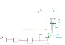
like this?

HiLoHeadlamps_zps713c7dd7.webp

I forgot the fuse on the wire from the solenoid/bus to the relay, the one to the HL switch should be covered by the fuse in the fuse panel, right?

I THINK I am going to put in a power bus on the fire wall for some of the + connections, to reduce :dung: on the battery post itself... there will be a - bus as well... front and aft for good negative return paths

You are, without doubt, the fastest learner or you have some experience with electrical you weren't telling about...

With a fusible link/fuse to the High Beam supply to the relay, your diagram is pretty much dead on.
You simply jump headlight POWER at the dimmer switch to low beams, just like in your diagram,
And add a relay to the high beams.

That way the factory headlight switch isn't trying to power BOTH sets of lights at the same time.
One set was marginal, both would be too much,
So the relay takes the load off the switch and you can SAFELY run the high beams the same time the low beams are on for more light.

A dedicated 'Ground Path' wire run to the grill shell for EVERYTHING up front will also increase both light output and RELIABILITY.
The front harness has a 'Ground', which screws to the grill shell, connect to that 'Ground' and your light issues should be a thing of the past.

The dimmer switch can fail, and you will still have LOW BEAMS this way.
The ONLY things that can kill your low beams is a switch or power supply failure.

Headlights are sacred, you MUST make them as reliable as humanly possible...
And you know there are 'Lights Went Out' threads all the time, pretty regularly.
This makes those a thing of the past.
 
Just a note on your diagrams, which you are quite good at for never doing this before,
You don't have to show a wire Jumping another wire/circuit when you use DOTS as connections.

A dot is a connection, without a dot, there is no connection, the wires/circuits just cross with no connection.

There are several disciplines of diagram/schematic drawing, just like there are several disciplines in the electrical community,
AC, DC, Welding, Micro, ect.
Dots and Jumps are mixing disciplines.

It's fine for Jeep stuff on a forum, but if you decide to work in a SPECIFIC field, it's good to know...

Schematics are PRECISE electrical 'Blue Prints', and after 45 years I still screw them up all the time forgetting what group I'm working with.

A 'Diagram' is a GENERAL wiring road map, you still have to obey the traffic laws, but this gives you a pretty good idea of what you are doing and where you are going.
Diagrams is what I post for the Jeep guys, it shows representations of the components they are working with.

When they recognize the starter, starter relay, distributor, headlights, ect. they are MUCH more at ease than with the Schematic symbols for those things.
Showing the bottom of a relay, with numbered terminals is much better for the guys doing this the first time,
They don't have to figure out which wire goes where!

i actually WAS an aviation electrician in the USN back in the 80s... worked on F-14s... but its not the same...

it is but it isnt... theres alot of AC on an A/C and MOST of what we did was change computers and gauges... it was VERY rare that we actually had to fix an open circuit... considering theres over 15 miles of wire PER Tomcat, thats a lot of wire to be chasing...

thanks for the kindness on my diagrams... i have been a shovel (civil) engineer (NOT a P.E. though) for several years, so i understand the importance of labeling and clarity... plus, i LOVE to draw/design stuff...

im just not any good at it in a practical sense... just because i can draw it, doesnt mean i can MAKE it...

in saying that... is this diagram correct as for the wiring for the lights?
 
Perfect diagram for the lights.
The only thing not included was the Fuse, and what kind of beer you are drinking after it's done! :chug:
 
i gave up drinking 315 days ago... so i'll enjoy a wal-mart fuzzy water... the fruit flavored carbonated water...

good to know its correct, and thanks!

i got my dedicated negative return box installed and wired up the rear marker lights... wired them into the negative box and they BOTH work with + applied to the tail/parking light post on the lamp switch...

once i get my relays in from DelCity, i'll start on the headlamps...

seems to be going a bit easier, but i know i'll have more questions as i go...

thanks TR for the help!
 
TR-

got my relays and LEDs in...

heres a question...

i want to use the LEDs as indicators for high beam, turn signals, parking brake and 4wd indicators...

they are here

LED Indicator Lights - Pre-Wired

they are rated at 15 mA at 12V... will i need to add the 1000 ohm resistors in order for them to work properly, or can you tell from the description IF they are good to go as they are?

i cant tell from the description...

thanks TR!
 
99% of this is off the top of my head, no issues, but now you are making me WORK for the stuff! :D

I didn't see any specifications tab to click, where are you getting the resistor rating from?

The trick with LEDs is...
They only hook up one way. They are diodes, so the current will only go through them one way for the LED to work.

Secondly, if you want to prolong life of the LED, you add increasingly larger resistors until you see the LED *SLIGHTLY* dim...
This is a REAL pain to do unless you have a ton of resistors laying around.

Hooking them up directly will usually work fine, and you will have longer life out them than the Jeep!
They live a REALLY long time, so you really don't have to add a resistor,

With the exception of maybe the bright light indicator,
And only then if it shines directly in your face.
Something real bright in your face is annoying, and for no other reason than that do you need to dim the LEDs.

"Ultra Bright" and 'In Your Face' sometimes conflict...

the rating came from the E=I/R (using 15V = .015A/R as my starting point) as the mA for the LED was so low, i didnt want to burn it up as soon as i put power to it... just trying to be safe

i DID get them (LEDs) from DelCity, so i know theyre 12V specific (i think thats all DC carries)...

i'll probably mount them down on the dash to keep them from shining in my face directly... i do know theyre bright...

thanks for responding...

what you may or may not know is that youre wiring my jeep by proxy! and and i REALLY appreciate the help!

mk
 
Last edited:
Most of the "12 Volt" generic LEDs sold by autoparts places are direct wire,
No fiddling with resistors...

I buy my stuff from Surplus places, Radio Shack, ect.,
When you get a 60 pack for $5, you have to expect some fiddling with them to keep things working...

One 'Sneaky' way to do a LED is a wide range variable resistor,
Start at MAXIMUM resistance,
SLOWLY turn the power up until you get in the range that makes the LED work without smoking it,
Then test the variable resistor to get you in the range for fine tuning.

Gets you in the range where you need to be without a bread board and 200 different resistors doing a 'One At A Time' test to get there.
I can never remember the band values, so it's even slower for me, I have to look EVERYTHING up...
 
I don't want to confuse things here,
But just looked this up for another user (PM, not open forum)...

When you get to the charging system, and *IF* you kept the Delco Remy SI altenator that most AMC CJs came with,

Delco Remy SI,
The 'Excite' or #1 terminal uses a 10 to 15 Ohm resistor wire from the factory,
It's small, stiff, Brown.

Your 'Painful' or none of the other 'One Size Fits Nothing' harnesses send that resistor wire, and they don't send you information on how to deal with that wire.

This is the QUICK way around the block,

SIdiode01.gif


Notice the 'Stripe' on the diode is 'Facing' the alternator plug?

The diode is Radio Shack p/n 276-1143.

This ELIMINATES the need for the resistor wire entirely.


---------------------------------

---------------------------------

Delco Remy CS series alternators are different.

Jeepers often swap in the Delco Remy CS alternators for better charging at lower RPM,
And it's almost a 'MUST' when you switch to fuel injection.

The 'Excite' or 'L' (Lamp) terminal MUST have somewhere between 75 Ohms and AMC 150 Ohms at 1/4 watt resistor for the voltage regulator to live.

This includes the 'Oval Plug' and 'Rectangle Plug' versions...

The resistance value went up as the CS alternators got larger,
The smaller ones were around 75 Ohms, while the very large are AMC 150 Ohms,
AMC 150 is 'Safe' for all, but the unit might not charge as well at lower RPMs.
 
Last edited:
Here is about as simple as it gets for headlight relays...

headrelay04.gif


This particular image shows a Fusible Link where a Self Resetting Circuit Breaker should be, but even I make mistakes regularly!

-------------------------------

I went with factory style 'SEALED' relays since they are right in the front that sometimes is under water in my Jeep, and virtually every time we go out, gets water slung all over them.

These are GM factory from Hella and are VERY good quality.
I swiped them off '89 Cadillac in the boneyard, but you can get them new from about any parts store or GM dealership.

SalvageRelays03.gif


SalvageRelays04.gif


The good thing about raiding the bone yard is you get the sockets, gaskets, mounting brackets and relays all for a buck or two.

If you do any real wheeling, then having SEALED relays that actually have a latch on them to keep them connected even when you are dealing with rough trails is a real plus!

relaygraphic01.gif


If you use the 'Discount Store' relays, look for name brands,
Hella, Bosch, ect.
The cheap 'China' relays will hold the amperage required for headlights, but they aren't made to last very long and sometimes have wiring defects internally that can cause you to pull your hair out trying to figure out what is wrong!
---------------------------------

Circuit protection is ALWAYS a concern!
Anytime you use circuit protection, it should be as close to the current source as is practical.

As in, for headlight relays that draw power from starter relay Positive battery cable terminal
(most practical place to tap for power in this instance)
You should have the Fusible Link, Master Fuse or Circuit Breaker as close to the Starter Relay as possible...

relay-breakers02.gif


I use SELF RESETTING circuit breakers myself, it's a safety issue.
The LAST THING you want to do is have a fuse burn and put all your lights out at highway speeds at night!

Fusible links are OK for bright lights, driving lights, ect.
But PRIMARY LIGHTS (Low Beams) SHOULD ALWAYS BE ON A SELF RESETTING CIRCUIT BREAKER!


Now, this is VERY easy to do, it's as simple as crimping on two female spade terminals and plugging in the circuit breaker!
Here are two Self Resetting Circuit Breakers attached to a common relay ready to install...

relay-breakers01.gif


One Side Note,
The breaker will work either way, but the 'Correct' way is with the copper terminal being powered, and the 'silver' terminal being 'Load'...

--------------------------------------
 
good info!

and i'll keep these in the bookmark til i'm ready for the front end... i've done about all i can do aft of the seats... still have the wiper and blower switch to install, as well as the LEDs, but thats pretty easy...

once i get the engine back and the tub mounted, i can do the rest of the front end stuff...

what i NEED to do is copy all this to word and make a book out of it

once again, thanks for the hard work and info... there will be more questions once i get to the steering column im sure... but i'll try it on my own 1st...
 
another question for you TR...

understanding the need for fused circuits coming off of the starter solenoid, could one of these be used instead of having a bunch of dangling fusible links all attached to the solenoid terminal?

ATC and ATO 6 Ganged Fuse Block

ATC and ATO 6-way Standard Fuse Block

it will keep things up and neat under the hood or on the interior firewall...

I would use the I=E/R to find the amperage for the circuit and protect it accordingly... which, if I remember right, is the next Higher (or same) fuse value over the amperage..

example: 30A circuit, install a 35A (or 30A) fuse for that specific circuit

that would be ok, right?
 
You don't have to use a fusible link for everything,
And a Positive Buss isn't out of the question.

The fuse block is a buss, with circuit protection.
SO, YES!
For Auxiliary circuits you don't have a fuse under the dash for, those little add on boxes are great...
The biggest issue I have with them is the feed cable, or the buss in the fuse block, usually isn't big enough.

I use them for my electric fan, electric fuel pump, headlight relays, ect. and the little feed buss with fusing works VERY well for those things...
I use the one I can feed with my own wire, something reasonable size for (in my case 6) 20 or 30 amp circuit breakers.

Fuses are fine, but I like circuit breakers.
The electric fan sees deeper water than I anticipated, it's going to pop the breaker,
Then come back on automatically...
(Hopefully I'm out of deep water and it doesn't just pop the breaker again...)

I use a FUSE on the fuel pump. Don't want that fuel pump coming back on just in case it's a pinched wire or some tree limb got into the pump screwing up the wiring,

Main lights, like headlights, are on breakers.
I want them back on, even momentarily, as soon as I can get them!
Let them go right back out if something is seriously wrong, but the second or two of light might keep me from driving into a ditch or something.

You have the right idea, this is all personal preference.
Use it, don't use it, doesn't fit your application, that's fine, it's just information for you to do with as you please.

My secondary fuse/breaker block is up front, lights, fan, air compressor, ect. are all mostly up front, and what's not, it's not hard to run a wire to that stuff.

This is for me only, just an idea,
Fusible link to the fuse block on the DRIVERS side fender, where there is some real estate that isn't cluttered,
Short runs from fuse block to realys, close to headlights, my electric air compressor is on the fire wall next to the brake master cylinder, so it's close,
The electric fan is between grill and radiator,
So the breakers/relays are all centrally located for me.

If it was JUST lights, the relays/breaker would be mounted on the grill shell.
In fact, when I do JUST lights, the relays/breakers are usually on the PASSENGER side mounted on the grill shell.
Makes wiring more convenient.

My electrical was WAY out of hand, I have a TON of electrical gadgets, winch controllers,
Isolated dual batteries, Electric fan, ect.
So when I rewired the Jeep, I just found real estate where it came easy,
Then worried about where things were going to go.
The fuse block on the flat surface, Relays on the vertical surface above it.
 
Last edited:
sounds like a plan...

I'm going to soft mount my battery tray and see what kind of room I have for things and install protection where I can get to it easier... some will be under the hood, some will be on the interior firewall...

can I just substitute a self-resetting breaker for a fuse if I want? I REALLY like that idea for the headlights

on this picture, what are the breakers protecting?

http://www.junkyardgenius.com/wiring/Images/relay-breakers01.gif

I don't understand whats going on here other than 2 CBs mounted to a relay... for what purpose?... what ckt is this on? are the breakers wired to the relay that they are protecting?

I want my electrical to be EXCELLENT in reliability, and using your methods is really going to help

mk
 
I use self resetting breakers in my lights.
Works well.
 
had to take a break to let the jolly old elf do some shopping for things that are NOT JEEP parts...

but he came thru for me under the tree!

got me some LED tail lights... very nice, but the wiring is all backward... WHITE is NEG!... once i got it figured out everything worked great... VERY bright... will only have to cover the PS bottom (where the DS shines on the tag)...

hope to get them installed in the next couple days...

engine is ALMOST ready... is fully assembled, but adding some parts and having the re-builder install them... plus, i dont get vacation til the boiss gets back, so i cant do anything with it anyway...

also got a 6 fuse ATC block for some stuff and my relays for the headlights... am thinking i will mount it all INSIDE on the firewall to keep them out of the weather...

hope EVERYONE is having a MOST merry christmas!!
 

Jeep-CJ Donation Drive

Help support Jeep-CJ.com by making a contribution.

Help support Jeep-CJ.com by making a contribution.
Goal
$200.00
Earned
$0.00
This donation drive ends in
0 hours, 0 minutes, 0 seconds
  0.0%
Back
Top Bottom